Where to place the responders
The geometric arrangement of responders determines the
“dilution of precision” (DOP, or noise gain),
that one can expect in various parts of the volume of interest.
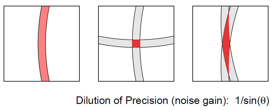 On the left is the annulus within which the initiator position is
constrained when a single, noisy distance measurement is available.
In the middle is the situation when two measurements are available
from responders that are more or less at right angles in directions
as seen from the initiator. Plausible solutions in this favorable case are confined to a
small area. On the right is the less fortunate situation where the
directions to the responders are similar, and not much new information
is provided by the second measurement. Correspondngly, the likely
position of the initiator is not as well confined.
On the left is the annulus within which the initiator position is
constrained when a single, noisy distance measurement is available.
In the middle is the situation when two measurements are available
from responders that are more or less at right angles in directions
as seen from the initiator. Plausible solutions in this favorable case are confined to a
small area. On the right is the less fortunate situation where the
directions to the responders are similar, and not much new information
is provided by the second measurement. Correspondngly, the likely
position of the initiator is not as well confined.
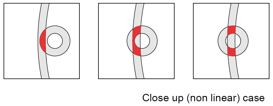 When close to one of the responders, the geometry becomes more
intricate, and, counter-intuitively, the solution may be less well determined.
When close to one of the responders, the geometry becomes more
intricate, and, counter-intuitively, the solution may be less well determined.
It is generally not a good idea to have all the responders close together,
since then the distance measurements will be correlated and somewhat redundant.
The effect of errors typically not isotropic, but is stronger
in some directions than others
(as, for example, in the case of GPS, where the vertical DOP is considerably larger
than the horizontal DOP, as a result of the fact that the “visible”
satellites are not distributed evenly over a sphere of possible directions).
In some cases ellipses of constant error may be quite elongated, meaning
that while the position may be well determined in some directions,
it is not in others.
Finding the “best” layout of responders in a given 3-D volume is an
open research problem.
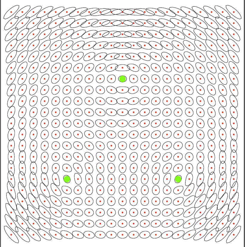
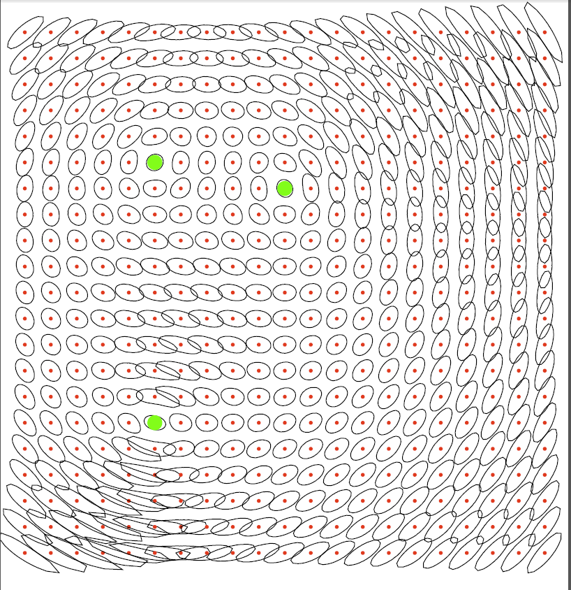 In the above 2-D examples, the green spots are the positions of responders
(APs), while the red dots are potential positions for the initiator
(smartphone, STA).
The constant error ellipses
show how position may be poorly localized in some direction yet well
constrained in a direction at right angles.
In placing the responders, the aim is to make the constant error ellipses
small and round in most of the work space.
Symmetrical layouts for the responders seem to work well, as shown on the left,
while somewhat suprising results may be achieved with asymmetrical layouts,
as shown on the right.
Note also that the method is useable even outside the convex hull of
the responders — up to a point.
In the above 2-D examples, the green spots are the positions of responders
(APs), while the red dots are potential positions for the initiator
(smartphone, STA).
The constant error ellipses
show how position may be poorly localized in some direction yet well
constrained in a direction at right angles.
In placing the responders, the aim is to make the constant error ellipses
small and round in most of the work space.
Symmetrical layouts for the responders seem to work well, as shown on the left,
while somewhat suprising results may be achieved with asymmetrical layouts,
as shown on the right.
Note also that the method is useable even outside the convex hull of
the responders — up to a point.
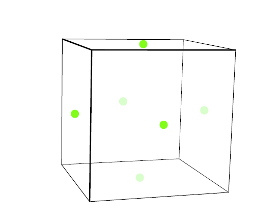
For a 3-D, cubic volume of interest (or a rectangular brick shaped volume with
not-too-different side lengths),
placing four responders at the vertices of a tetrahedron embedded in the cube
has appealing properties (these points are at the four “even” vertices of
the cube — see left figure below).
With six responders, the vertices of an octahedron have good properties
(these six points are at the face centers of a cube — see right figure
below).
Both of these configurations avoid placing any subset of (more than three)
responders in a plane.

 Adding a responder somewhere in the middle of the volume also improves
overall position accuracy.
Adding a responder somewhere in the middle of the volume also improves
overall position accuracy.
Placing responders at regular intervals along a line,
while providing simplicity of installation, is not a good idea
if position accuracy is of importance.
Click here to go back to
main article on FTM RTT.
Berthold K.P. Horn,
bkph@ai.mit.edu
Accessibility