How much of an improvement can be expected?
The signal at the cell phone after installation of the repeater should be
higher than it was without the repeater. Some cell phones provide detailed
information on signal strength (SSI), signal-to-noise ratio (SNR) etc.
On some phones, the signal strength can be measured before and after
installation of the repeater using e.g.
*#*#4636#*#* and/or ‘Phone Information > Signal Strength’
or using an app like
CellTracker
(or say OpenSignal).
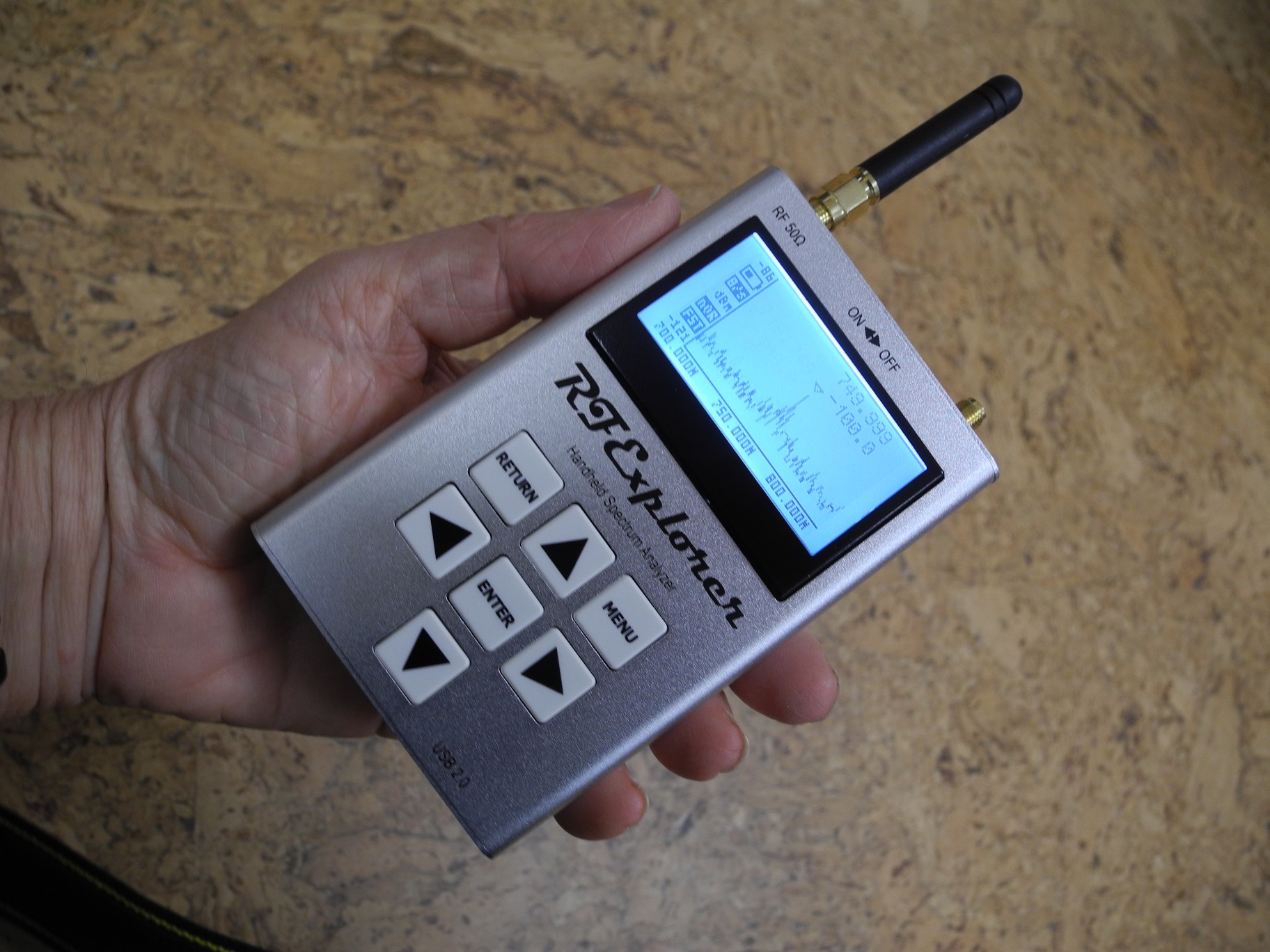
Another alternative is an RF signal strength meter such as the
RF Explorer:
The whip dipole antenna — see left image above —
that comes with the Combo models is tuned to 2.45 GHz and not useful for
“cellular” frequencies (824-894 MHz).
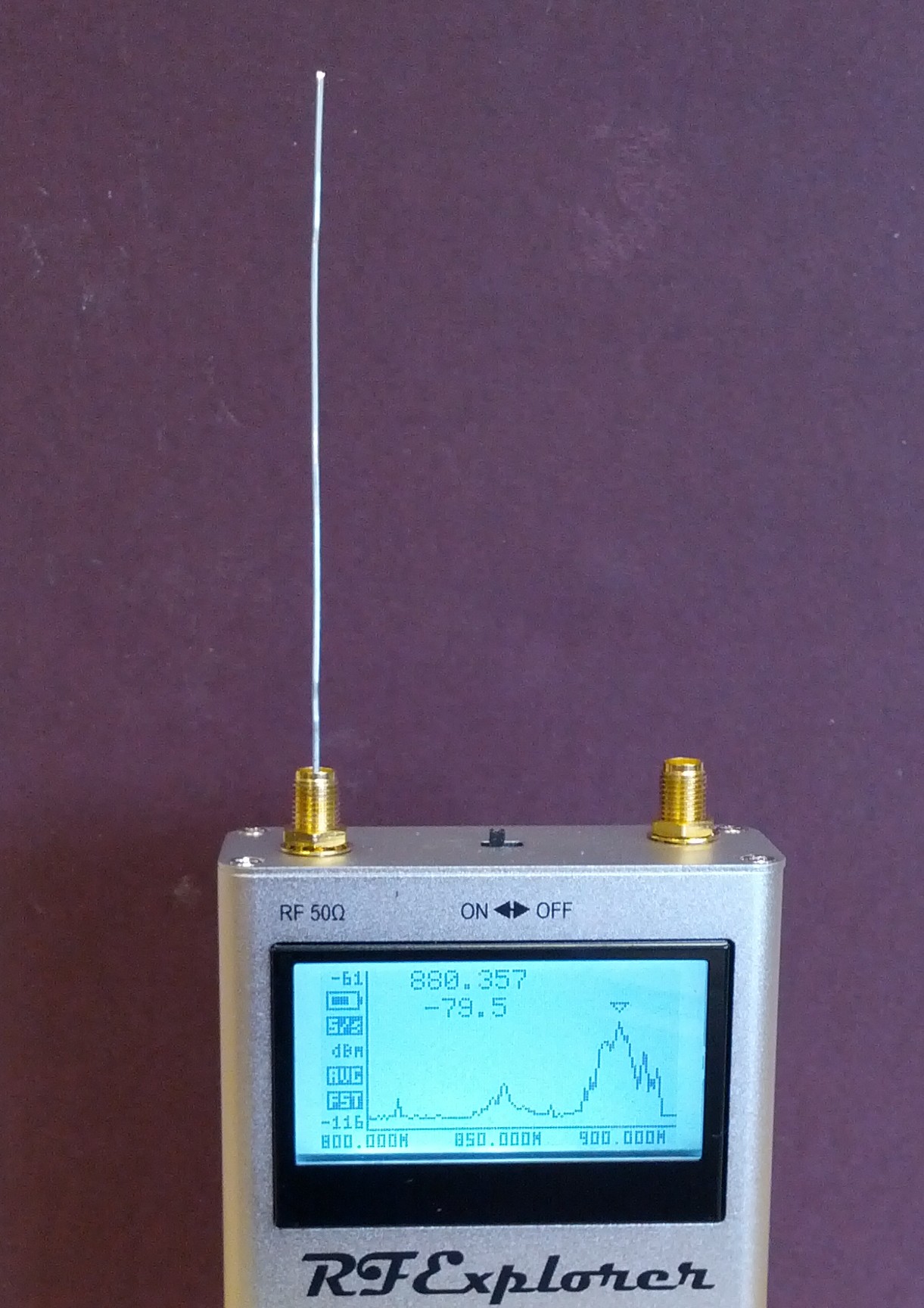
An unfolded paper clip — see next image above — works better
(about 88 mm — a quarter of a wavelength at 850 MHz —
plus a couple of mm to go into the connector).
Smooth off sharp edges on the end of the wire that will go into the SMA connector to avoid damaging it.
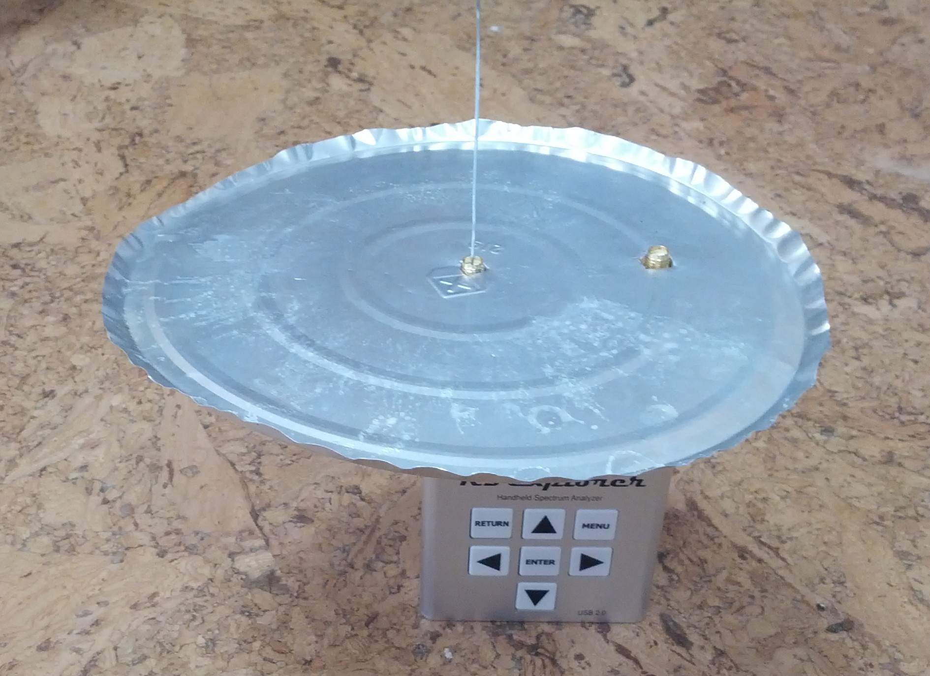
An improvised ground plane — see next image above — increases the sensitivity a bit.
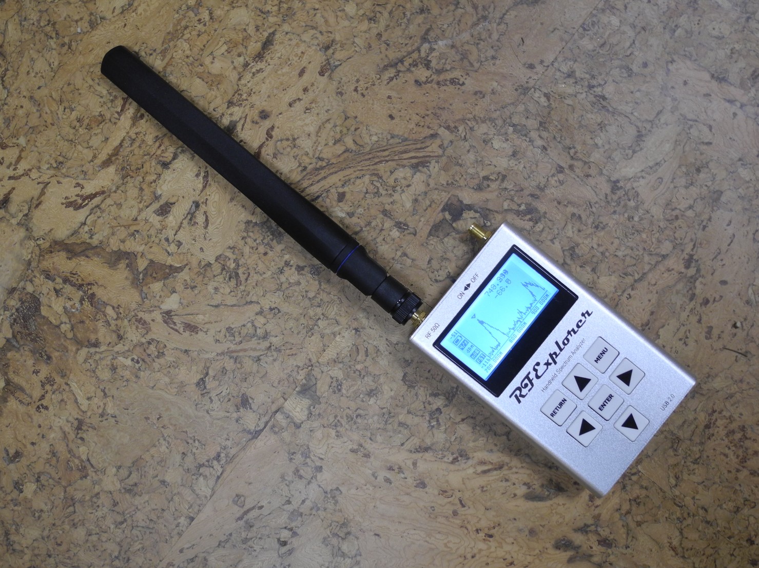
For a more professional looking alternative, get the
Mobile Mark PSKN3-700/2100S half-wave dipole with SMA connector — see
right image above.
Look in the downlink range of frequencies for your carrier, where there should be a lot of activity —
e.g. for CDMA “cellular” (Band 1) it is 869-894 MHz downlink (with 824-849 MHz uplink),
while LTE band 13 is 746-756 MHz downlink (with 777-787 MHz uplink)
and LTE band 12 is 729-746 MHz downlink (with 699-716 MHz uplink).
Note that some carriers (e.g. U.S. Cellular) have “refarmed”
the 3G voice “cellular” Band 1 to use for data (LTE Band 5).
This tool can be an aid in antenna aiming, as well as comparing antennas
(and checking on claimed gain figures).
Keep in mind though that the signal strength tends to be constantly changing
(since it depends on how many other users are connected to the base
station, how far away they are, propagation conditions, etc.),
so at the least, some form of averaging over time is called for
(particularly when the connection is not LOS).
Another option is the
Wilson RF Signal Detector 867501
(*).
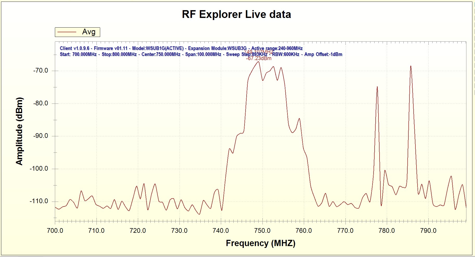
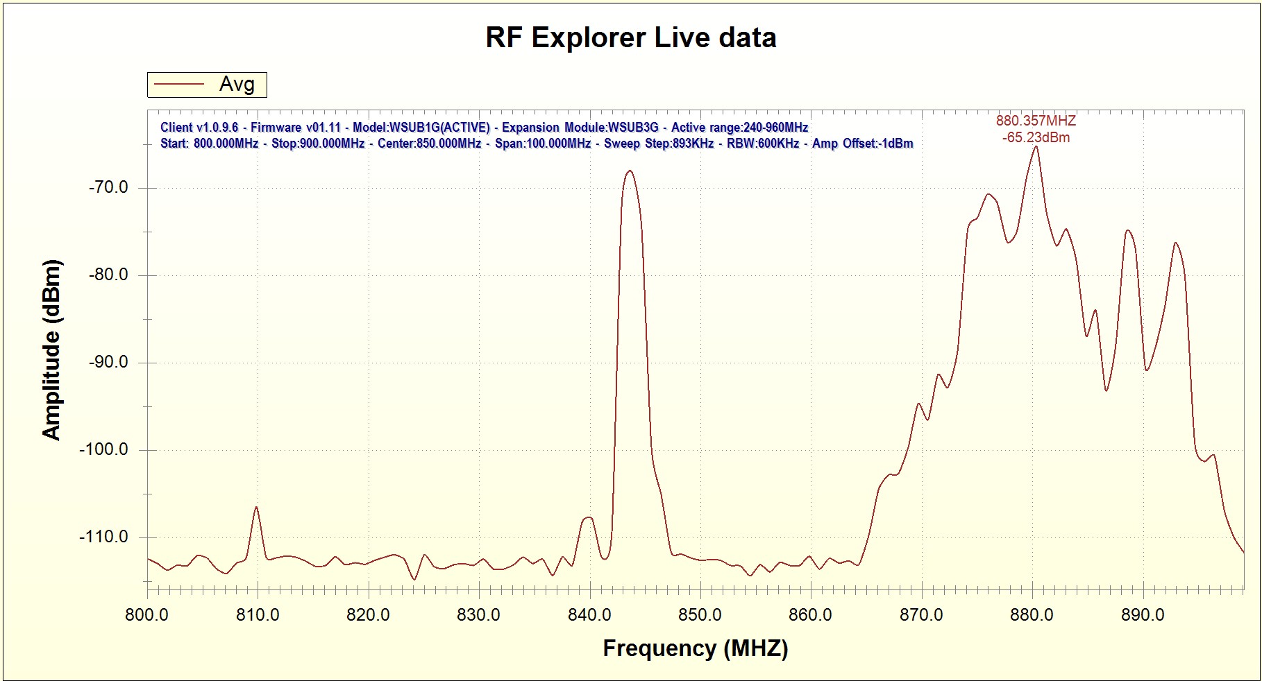
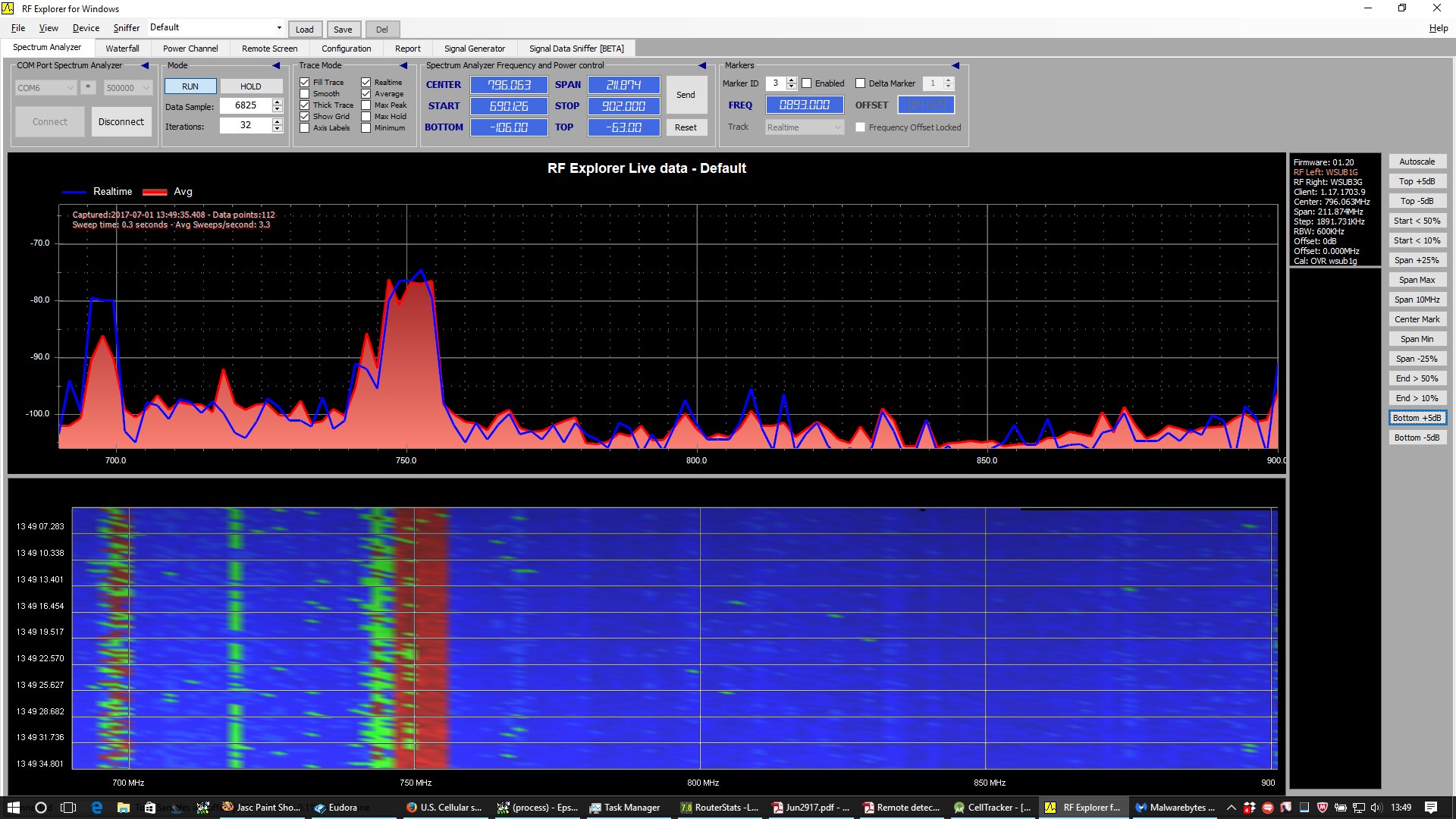
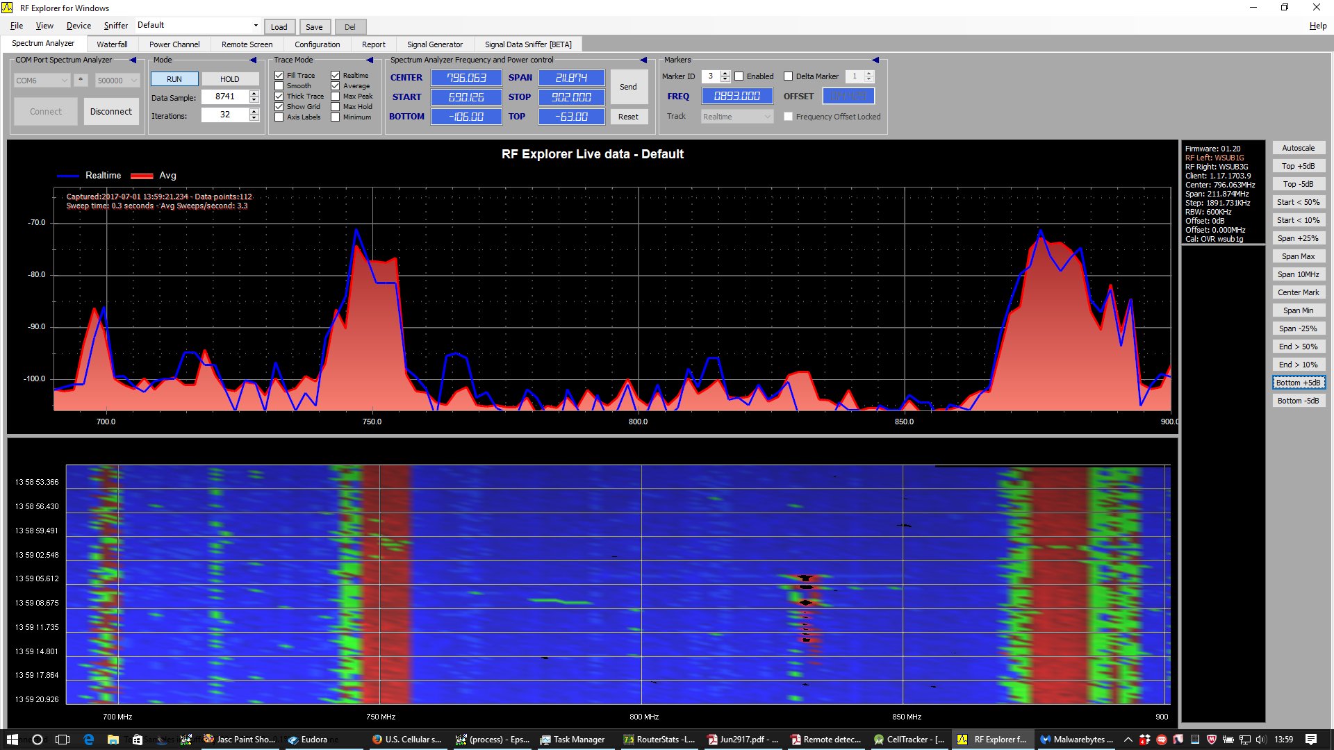
Sample Graphs from RF Explorer
On the left above: upper 700 MHz Band (LTE Band 13).
On the right above: 850 MHz Band (3G “cellular” Band 1; LTE Band 5).
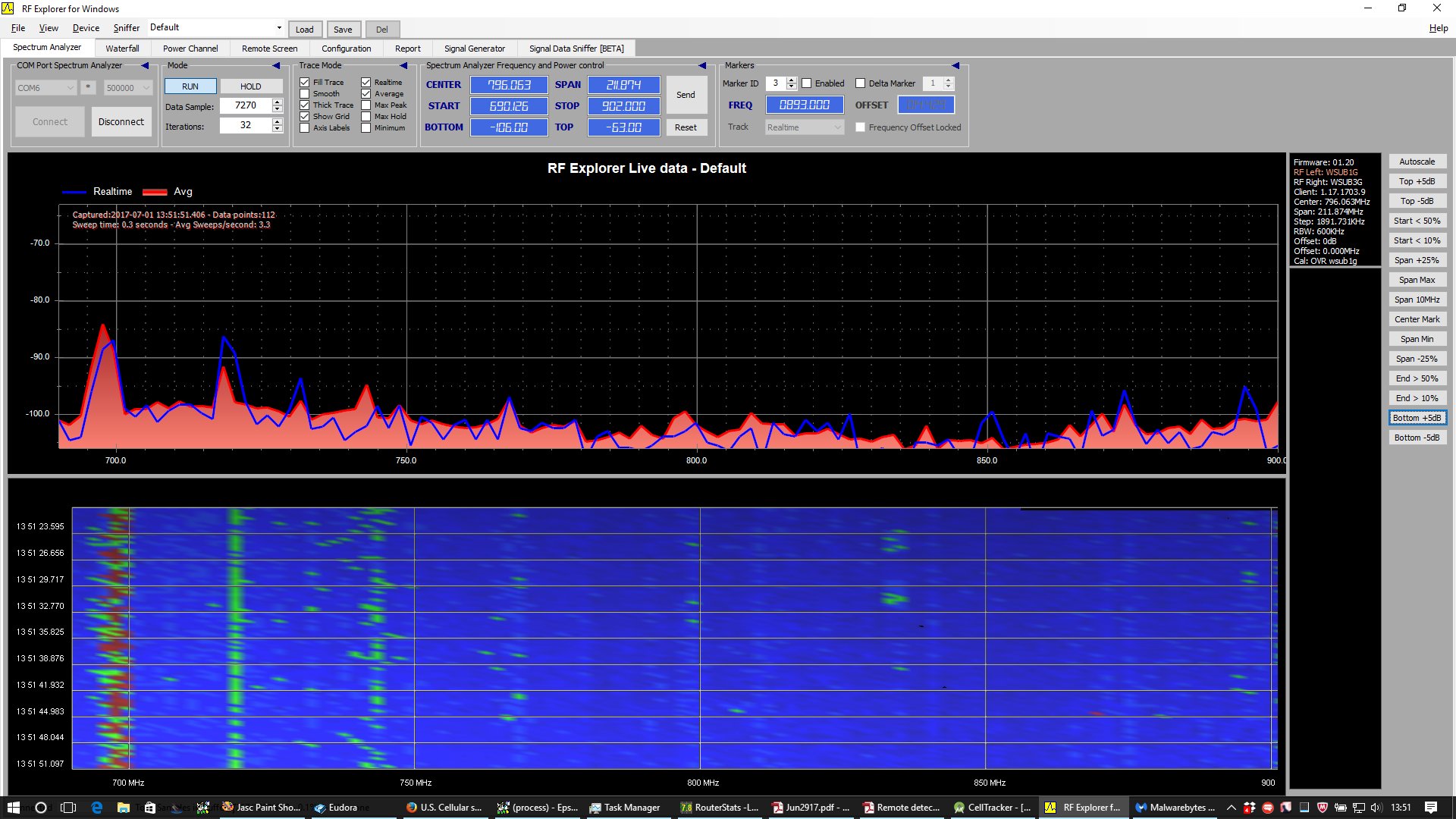
Left above: both repeaters shut off, just some background noise
around 695 MHz and 720 MHZ caused by nearby laptop.
Right above: 800 MHz repeater turned on
(strong DL signal in the 869 - 894 MHz range).
Left above: 750 MHz repeater turned on (strong DL signal in
the 746 - 756 MHz range).
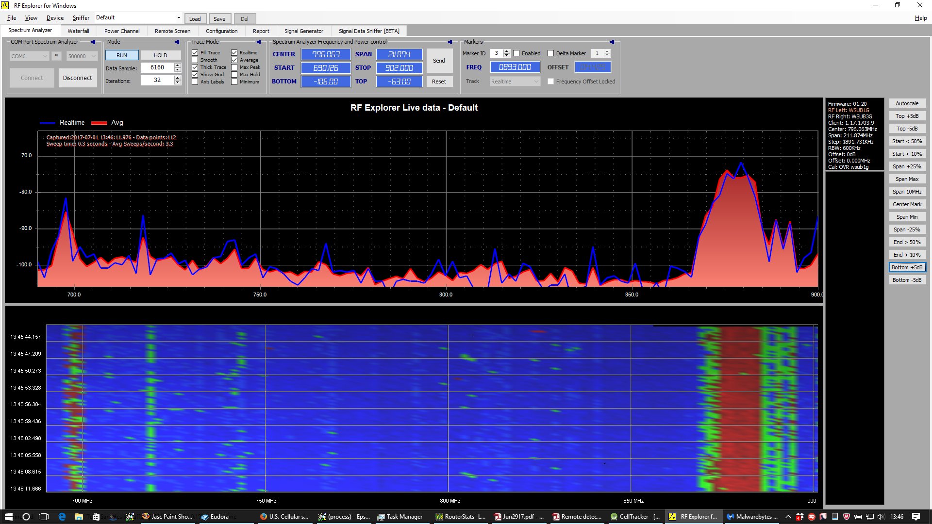
Right above: both repeaters turned on.
Note also UL signal from UE in the 824 - 849 MHz range
caused by nearby phone uploading image to FB.
Effective Area and Gain
An antenna has an
“effective area”, which is the ratio of the
power delivered at the output of the antenna
to the power per unit area of the incident radiation.
(For detailed discussion of the properties of antennas see
“Outside Antennas”).
Put another way, the antenna delivers as much power as passes through
a patch having the stated effective area.
The effective area is related to the antenna power gain,
where λ is the wavelength, and G is the power gain
(as a ratio, i.e. not in dBi —
the gain in dBi is given by g = 10 log10(G)).
A
half-wave dipole,
for example, has effective area
0.1303... λ2
(since 2.14 dBi corresponds to a power gain of 1.64...)
The effective area can be a useful quantity when doing calculations
based on known base station antenna power, base station antenna gain, and
distance (if the path — and the first
Fresnel zone — is unobstructed).
The power delivered by a transmitting antenna to a receiving antenna
is proportional to the product of the effective apertures of the two antennas:
where r is the distance between the antennas, λ the wavelength,
Pt and Pr the transmitted and received power
respectively, while At and Ar are the effective areas of the
transmitter and receiver antennas.
(Note how the effective areas have to scale with wavelength to achieve
the same ratio of received to transmitted power).
This can also be rewritten in terms of the antenna gains as
Pr = λ2 / (4πr)2
Gt Gr Pt
where Gt and Gr are the gains of the transmitter and
receiver antennas respectively.
Simplified repeater power density gain calculation
By how much does the cellular repeater setup increase the power density?
Suppose the wave incident on the outside antenna has power density
Din
(W / m2).
Then the question is what is the power density
Dout
of the radiation at a distance R from the interior antenna?
First, the power received is
where Aeff, as given above,
is the effective area of the exterior antenna.
This input power is then amplified by Gamp
by the bi-directional amplifier and sent to the interior antenna.
So the power radiated from the interior antenna is
Pout = Pin Gamp
= Din Aeff Gamp
or
Pout = Din λ2 / (4π) Gin Gamp
If a cell phone is a distance R from the interior antenna,
where R is many wavelengths (*),
then the power density will be about
Dout = Pout Gout / (4π R2)
where Gout is the gain of the interior antenna.
Hence, overall, the ratio of power densities is
G = Dout / Din =
λ2/(4π R)2 Gin Gamp Gout
Converting to dBs
we get
g = gin + gamp + gout
- 20 log(4π R/λ)
From this we would need to subtract a couple of dBs for cable losses,
coupling losses, and so on.
(*) The simple inverse square law formula applies only in the
“far-field”
(also called “radiation zone”), several wavelengths from the antenna.
Example
As an example, consider an outside antenna with gain 14 dB
(i.e. a factor of 25 in power), an inside antenna with gain 5 dB
(i.e. a factor of 3 in power), an amplifier with gain 60 dB
(i.e. factor of 1,000,000 in power), and a distance R = 20 λ
(e.g. 7 m at 850 MHz) between the interior antenna and the cell phone.
Then
g = 14 + 60 + 5 - 20 * 2.5 = 29 dB
or in other words about a factor of about 800 in power density.
That means that if one had about -100 dB without the repeater, then one can
expect about -71 dB with it. Of course, whether a good connection can be
made also depends on other factors, such as the signal-to-noise ratio (SNR).
(*) Wilson Electronics
has become
weBoost,
which may carry some of the above mentioned products.
See also RepeaterStore
Click here to go back to
main article on cellular repeaters.