In an effort to set up a cellular repeater in an area with no line-of-sight (LOS) connections to any cell phone tower, a number of different types of outside antennas were tried. This summary may help in selecting and setting up your own cellular repeater in an area of marginal signal strength.
First though, note that one use of cellular repeaters is to provide a useable signal inside a concrete and steel building when a perfectly good signal is available outside the building. In that situation simply use one of the many cellular repeater kits available (such as e.g. from RepeaterStore, Solid Signal, Wilson Amplifier Store, wpsantennas.com, weBoost, Phonetone, etc.).
Also, in some cases, where a good internet connection is available, a “femto cell” may provide an alternative solution (by the way, the distribution of femto cells can provide useful information about areas of poor reception). The discussion here is aimed at situations where the available signal is weak — such as in a rural area without direct line of sight to any cellular towers (and particularly where a high speed internet connection may not be available for setting up a femto cell). In this case, the outside antenna should have:
(2) narrow beam width — at least in the vertical direction.
Click here for detailed comparison of Outside antennas for cellular repeaters.
Click here for CellTracker, an Android app that provides useful base station antenna information.
First, if there is no detectable signal (or if it fades in and out between say -120 dBm and -100 dBm), then there is not much hope. Noise will be amplified as much as the signal — and amplifier noise is added to that — the result is unlikely to be useable. For success, the signal may be weak, but there has to be some sort of signal — one that doesn't frequently fade away below the noise level. Most cell phones have a way of providing some information about signal strength, e.g.
Fortunately, these days, there are numerous apps that provide signal strength information, such as OpenSignal, CellMapper, SignalSpy, G-NetTrack, and the above mentioned CellTracker (some, such as NetworkGuru, require a rooted phone). On some phones, one can also try ‘Cellular phone field test modes’. or search for “Field Test Modes” for your specific model.
It helps to wander around a bit to see what signal strength is in an area. It is best to do this as high in the building as where one is planning on mounting the outside antenna. Note that signal conditions may vary quite a bit with time. So best to repeat this exercise several times. Also, a good signal may come from unexpected directions, such as a reflection off a hillside away to one side of the straight line direction to an antenna. Unfortunately cell phones lack the ability to provide information on the direction of the incoming signal. There is some chance for success if the signal comes in stronger than say -100 dBm (think about it: that is 10 orders of magnitude below 1 milliwatt!).
Android apps such as CellTracker (see also OpenSignal) can be useful in that they provide detailed signal information, including signal strength indicator (RSSI or ASU), EVDO signal-to-noise ratio (SNR), and bit error rate (BER) for GSM or Ec/Io for CDMA. Importantly, they can also record a sequence of measurements in a file, along with GPS coordinates of the cell phone location.
To get continuous recordings of detailed information in the OpenSignal app, select ‘Menu > Settings > Data Sharing’ then check ‘Save cell data to SDcard on upload,’ and ‘Maximum background sharing.’ Also, select the ‘Map’ page in OpenSignal to make sure the GPS will be turned on, and make sure the screen stays illuminated. You can force the screen to stay on by checking
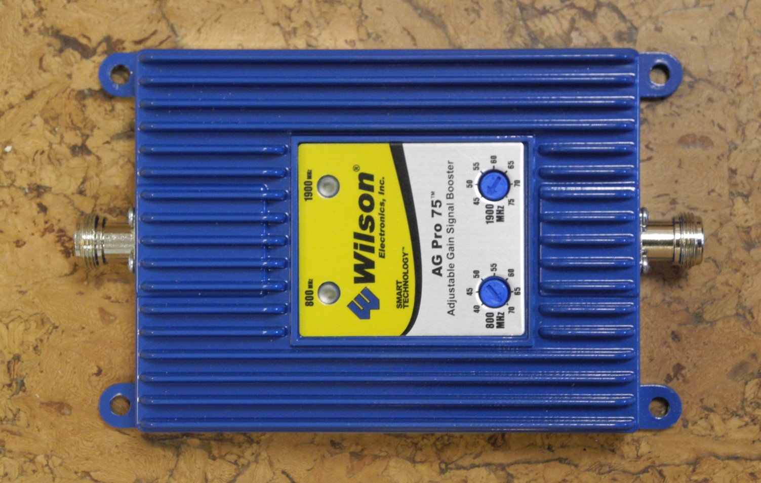
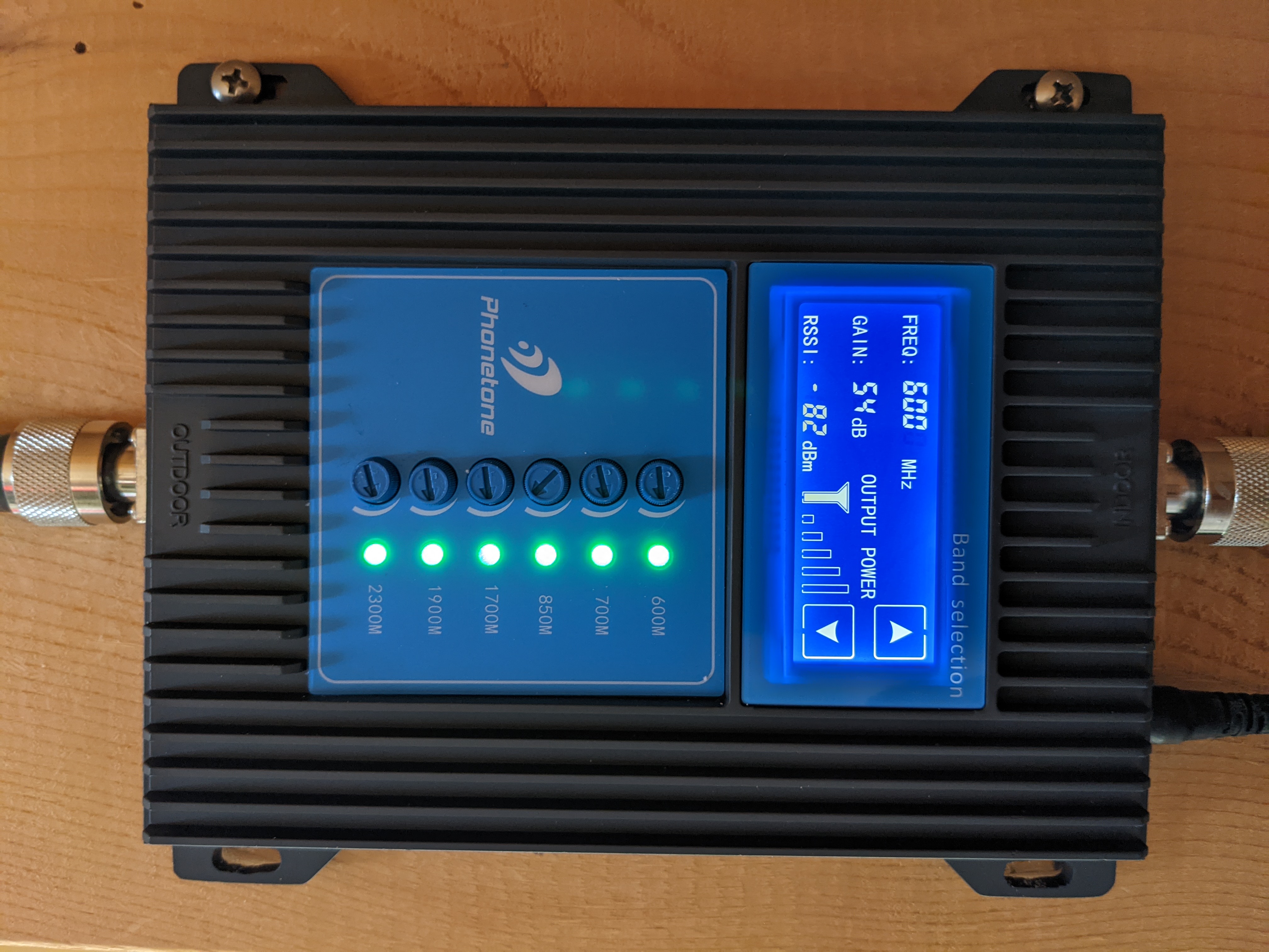
Next, a good bi-directional amplifier from a reputable manufacturer such as weBoost (formerly Wilson Electronics) is essential (bi-directional amplifiers exploit the fact that for many bands, uplink communication is on a different frequency band than downlink). The amplifier should cover the frequency band(s) used by the cellular carrier in the area (see below). When the signal strength is marginal, it is best to get the highest gain available. Examples include Connect 4G-X, formerly Wilson AG Pro 75), with 70 dB gain in the cellular band (824-894 MHz) and 75 dB gain in the PCS band (1850-1990 MHz)) (left image below) and Phonetone 7 Bands Signal Booster (right image below).
Note, however, that it doesn't help much to just amplify a very noisy signal, since both the signal and the noise will be amplified — and then amplifier noise is added to that. So it is very important to have an antenna of high gain (see below) to deliver as large a signal as possible to the amplifier, making amplifier noise less of an issue (the antenna itself does not add noise — no matter how high its gain). A high gain antenna of neccessity also has a narrow acceptance angle (see below), which limits corruption of the signal by electromagnetic noise sources away from the direction of the desired signal.
The bi-drectional amplifier should have ‘feedback/oscillation’ detection so it will shut down when the signal from the inside antenna(s) feeds back to the outside antenna with enough amplitude to cause uncontrolled oscillations (think microphone squeal). Having the ability to manually control the gain can be a nice feature since this makes it possible to turn the gain down to below where feedback oscillations occur, should it turn out that it is not possible to position the inside and outside antennas to avoid oscillations at the highest available amplifier gain. Some amplifiers automatically reduce the gain when needed.
(The FCC has to have approved the device and you may have to register it with your carrier — check the information that comes with the amplifier, and, if needed, consult your carrier).
It is not always easy to figure out what frequency bands the carrier uses in the area of interest, since they often operate in more than one band, and often don't make a point of advertizing which band is used where (see e.g. CDMA coverage). Fortunately, since Android API Level 24, Absolute Radio Frequency Channel Numbers is available: ARFCN for GSM, UARFCN for WCDMA / UTMS, EARFCN for LTE / 4G, and NRARFCN for NR / 5G. Use Niviuk's web site to convert RF channel numbers to actual frequencies (There is a lot of other useful information about cellular technology on that web site as well).
What band is used depends on the local situation. For example, higher frequency band may be used in urban areas to restrict the range of a particular antenna in order to curtail interference between closely spaced cells (higher frequencies are attenuated more by obstacles and do not diffract as well). Alternatively, both lower and higher channels may be used in order to provide more channels in heavily populated areas. In rural areas, on the other hand, a lower band may be used alone, both for historic reasons (earlier deployment and less frequent upgrading) and because longer wavelengths can provide a stronger signal in non LOS situations, as they are diffracted more at edges of obstacles. Verizon Wireless, for example, may use the ‘PCS’ (1850-1990 MHz) band in an urban area — or both ‘cellular’ (824-894 MHz) and PCS — but may elect to use only the lower (‘cellular’) band in some rural areas. In some major cities, Verizon uses the very high frequency bands 261 (28 GHz). Conversely, in rural areas, T-Mobile makes heavy use of the "digital dividend" band 71 (600-700 MHz) (freed up recently by moving UHF TV signals).
Fortunately multi-band bi-directional amplifiers are commonly available. It is easy, of course, to determine which band is in use, once a cellular repeater with multi-band bi-directional amplifier and antenna have been set up: Simply turn down the gain on one band at a time and see which one causes the cell phone signal to drop. Unfortunately, that information then comes too late to influence the choice of antenna or amplifier!
The next problem may be to figure out where the cell towers are, that, while not line-of-sight, produce a detectable signal. This is so that the directional outside antenna can be aimed properly. It is also useful for figuring out how wide a radiation pattern (horizontally) one might want to go for in the antenna in order to cover more than one tower — if there is more than one with enough signal to be potentially useable. It is good to have more than one tower in ‘view’ of the antenna, since the probability of signals from two sources fading at the same time is much lower than the probability that one will.
In some countries information about cell phone tower antennas is readily available. In Canada, for example, "Location xcelerated" (Loxcel) provides easy access to details such as carrier, frequency, bandwidth, power, height, antenna gain, cable loss and even azimuth of individual sector base station antennas (based in part on license records from Industry Canada which manages the frequency spectrum allocation). Similarly, Ofcom's Sitefinder used to provide information (although less detailed) for the United Kingdom. In the USA, the FCC unfortunately does not provide an organized data base containing this information.
One way to get some information about the ‘cell’ one is connected to use the Google Maps app on Android, select the menu, and then
For GSM this gives MCC:MNC LAC:CID (e.g. 310:660 15:25505) (where MCC is mobile country code, MNC is mobile network code, LAC is local area code, and CID is the identity of the particular antenna connected to). For CDMA this gives instead MCC SID:NID:BID (e.g. 311 28:5:781) (where SID is system identification, NID network identification, and BID is the base station identification).
Unfortunately this doesn't tell you where that antenna is, so another step is required. This is where applications like CellTracker come in handy (see also OpenSignal). Note that, in OpenSignal at least, the ‘tower locations’ reported are not the actual antenna coordinates — but the average of coordinates where cell phones were when they connected to that antenna (This makes sense for the primary application of such data, which is to provide a ‘location service’ for cell phones based on which antenna they are connected to).
Since most base station antennas are directional, there is a built-in bias in the average in the direction of the antenna's main lobe — as a result, some ‘tower locations’ may be quite far off the mark and even appear to be in the middle of a river (sample screen shot from OpenSignal app):
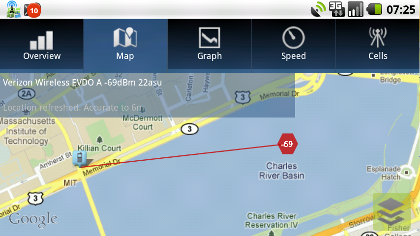
In many cases, the offsets in reported position are along major highways, since it is along roads that cell phones most often are when they detect the signal. The offset is particularly significant in rural areas where spacing between towers tends to be considerably larger than in urban areas.
CDMA-based carriers, such as U.S. Cellular and SPRINT, do provide the coordinates of the base station in the CDMA lat and CDMA lon fields. These coordinates are available to Android apps — and may also be visible via
Online searching for the location of local towers is possible (using e.g. AntennaSearch and TowerCo), but can be frustrating and lead to erroneous and incomplete results (e.g. FCC registration only applies to towers higher than 200').
In the process, it may be worth noting that a given tower often has ‘co-located’ antennas from several different service providers. More importantly, there are typically three uniquely identifiable antennas (i.e. with different BIDs for CDMA — or CIDs for GSM) from each carrier. These are typically ‘sector’ antennas aimed to cover three different ‘cells’ near the tower. Each antenna typically covers a 120° sector.
In general, when mapping out base station antennas in an areas, it can be helpful to know something about the numbering scheme used by carriers to assign “unique ID”. Because of the directional bias in the ‘tower locations’ provided by location services, the reported ‘locations’ for sector antennas mounted on the same tower (but aimed in different directions) may be quit different. A somewhat better estimate of the tower location can be obtained by averaging them.
Another way to find approximate cell tower locations is to use the Google Maps Geolocation API by probing it with an antenna identified by SID:NID:BID (for CDMA), MCC:MNC LAC:CID (for GSM), or MCC:MNC TAC:CI (for LTE). Once again, note that the reported location is not the location of the cell tower, but where cell phones where when they reported being connected to that antenna. In fact, one of the parameters returned indicates the size of the area from which cell phones reported ‘seeing’ this particular antenna.
It may be worth driving around a bit to find the actual locations of nearby towers. When doing so, keep in mind that signal strength does not just depend on distance from the tower, since the radiation pattern is directional, and also typically narrow in the vertical direction (see below). In some cases, for example, one may get a relatively weak signal when very close to the tower, because one is ‘under the beam’ (or near a null between side-lobes),
The cell phone system may be reluctant to switch to a different antenna (‘hand over’), even when it would provide a better signal (or lower signal-to-noise ratio), as long as it has a good enough connection to the antenna it is currently connected to. So one is not necessarily connected to the nearest antenna, or the one with the best signal at any given time — which antenna is currently selected is partly a function of the connection history, as well as the current load imposed by other cell phones on particular base stations.
It is also hard to force the cell phone to change which antenna it is connected to in order to ‘explore’ the neighborhood of antennas. Temporarily disconnecting, by, going into ‘Airplane Mode’ (altenatively ‘hiding’ the cell phone by putting it in a conductive foil pouch) may at times cause it to connect to a different antenna when it does become ‘visible’ again. Note, however, that the cell phone system tends to remember previous connections and may try and re-establish those.
Another thing to keep in mind (at least for CDMA) is that signal strength indicator (RSSI or ASU) is the ‘raw’ amplifier signal strength — based on the automatic gain control (AGC) level of the intermediate frequency (IF) amplifier. That is, it is not just the signal coming from the antenna one is currently ‘parked on,’ but everything in a particular RF channel. This helps explain why, when the phone system does decide to switch connection from one antenna to another, there is typically no significant accompanying change in ‘signal strength’ (RSSI or ASU).
When driving past a cell phone tower, one will, of course, tend to receive a relatively strong signal, but one will also typically be ‘handed over’ from one antenna (BID/CID) to another, since most antennas cover ‘sectors’ of less than 180° (typically 120°) and a road near a cell tower is bound to cross over a boundary between one sector and another (and may sometimes cross two boundaries in quick succession). Keep in mind though that it can happen that, while driving past a cell phone tower, and receiving a strong signal, one is actually still connected to an antenna on a different tower (particularly if base stations on the nearest tower are very busy). In this case one might be misled in identifying the currently connected BID/CID with the tower being passed. Fortunately this is not a common occurence and unlikely to happen on every trip past the tower.
Some carriers (such as U.S. Cellular and SPRINT) conveniently use consequtive BID/CID numbers for the sector antennas on a tower, while some others (such as Verizon Wireless) uses BID/CID numbers that are spaced 256 apart (increasing clockwise, starting from the sector aimed closest to North — see numbering schemes). One can obtain a slightly better idea of where a tower really is if one averages the ‘locations’ reported for the three sector antennas on the tower.
Click on the image below to see an example of a detailed map of a set of CDMA cell phone antennas in a rural area mapped out in this fashion and superimposed on a Google terrain map:
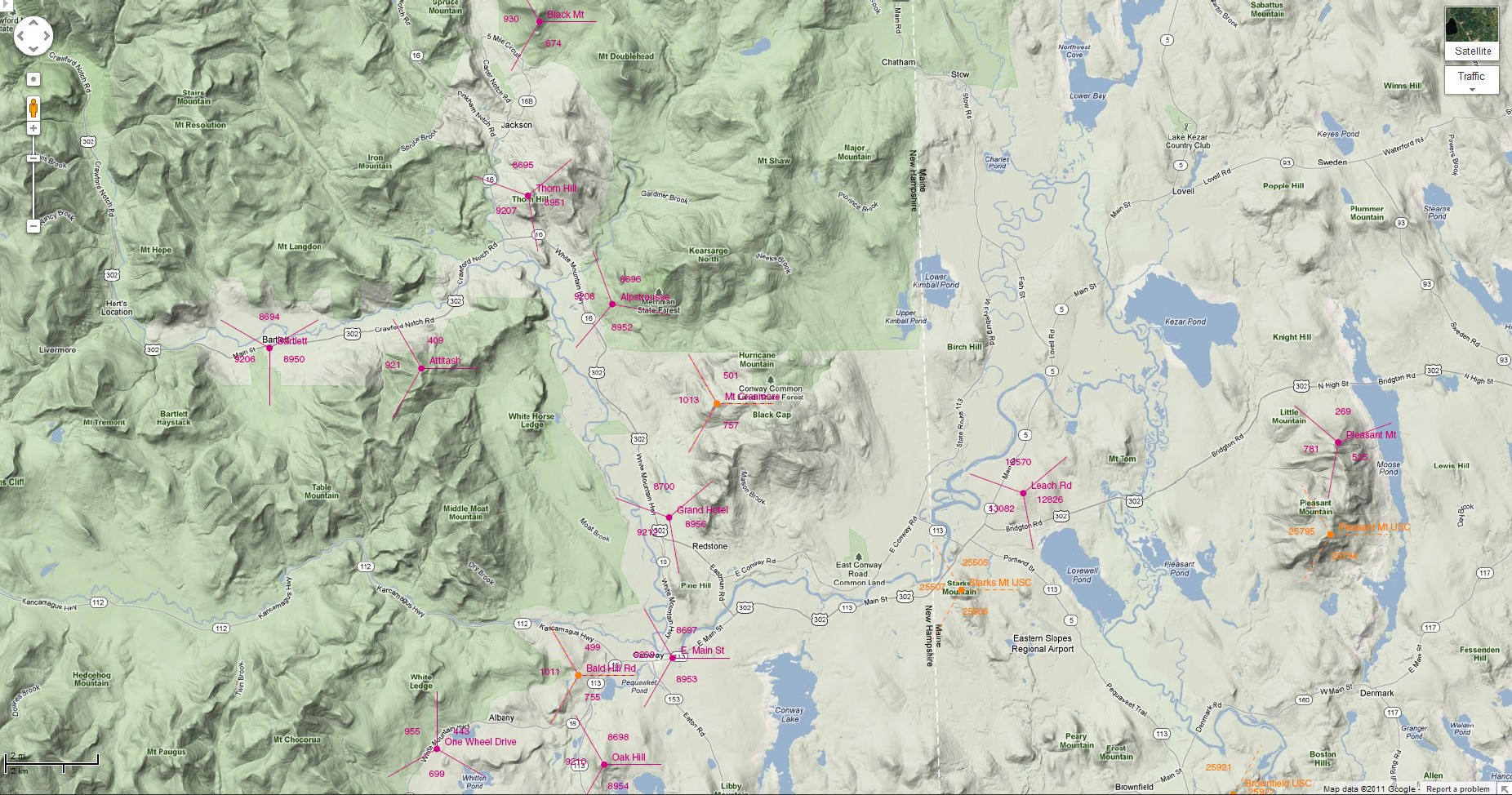
In the above map, the BID of each antenna is shown within the sector it “illuminates.” Red triads are Verizon Wireless, orange triads U.S. Cellular. Note that some of antennas of the two providers are “co-located.” Also, a couple of towers do not have the full complement of three sector antennas (because the third sector would cover an area devoid of roads).
The interior antenna should be far from the outside antenna, preferrably placed in a position that, when viewed from the outside antenna, is opposite that of the base station. The interior antenna can be somewhat directional (e.g. a flat panel or dome antenna) and mounted to “illuminate” the area where cell phones may be used — but preferrably not aimed back at the outside antenna.
If the amplifier gain cannot be turned up all the way without oscillation, then the antenna separation may need to be increased. Move the interior antenna as far as possible from the outside antenna, even if that means that it is not in the center of the desired coverage area. With the higher gain setting possible that way, the signal is going to cover a larger area.
In some cases, it may help to turn or rotate the interior antenna so that its polarization axis is not near parallel to that of the outside antenna (which is vertical). Don't know what the interior antenna's polarization axis is? In the case of a flat panel, it is usually the longer dimension of the panel. But in any case, one can just try different orientation to see whether the oscillation problem can be reduced in that fashion.
Sometimes metal (such as that in air-conditioning ducts) or thick concrete parts of the building can be used to “hide” the interior antenna from the outside antenna.
Despite what has been said above, sometimes too much amplification may be too much of a good thing. The reason is that the cellular system may not switch to a different antenna if it appears that the cell phone is getting a strong signal from the one it is ‘parked on’ — even if that strong ‘signal’ does not have good signal-to-noise ratio (SNR). If there are multiple weak signals available, then it may be better to crank down the amplifier gain a bit to encourage switching between them whenever the one one is currently connected to becomes too noisy.
What does that say about antenna gain? The antenna gain should always be high so as to provide a signal that is large relative to the amplifier noise — increased antenna gain does not mean increased noise.
With non-LOS communications, signals reaching the receiving antenna may have travelled over more than one path and so arrive at slightly different times — in effect the received signal has multiple ‘echos.’ Equalization in the receiver can compensate for this if the pattern of ‘echos’ stays constant. But non-LOS communication signals from multiple paths interfere with one another (constructively and destructively) in a time-varying manner — in the worst case leading to ‘fading,’ a temporary loss of signal. (Note that LTE has less of a problem with this because it uses low speed signalling over a large number of narrow channels and so the guard interval between bits can be made long enough to deal with quite a bit of multi-path ‘smearing’).
The variable nature of the signal induced as a result of it travelling over multiple paths has the most deleterious effect on higher frequency components of the signal payload. As a result, data transmission tends to be affected more than voice. One consequence is that with high gain in the antenna and the bi-directional amplifier, one may very well see a sizeable signal (high RSSI or ASU) on the cell phone, yet have relatively low data transmission rates (as reflected e.g. in low EVDO SNR and low Ec/Io).
More gain in the amplifier cannot get around this limitation. High gain in the antenna, on the other hand, can help, because it comes with a narrowing of the acceptance angle. The interference due to multiple paths is reduced if the antenna is aimed so that signal from only one of the multiple paths comes from a direction in which the antenna has significant gain.
Click here for CellTracker, an Android app that provides base station antenna information.
Click here to go back to main article on cellular repeaters.