Although controller generates the right signals for directing motors to their desired positions, these signals are too weak to drive motors. Therefore, control signals must be amplified before being used. Moreover, the rotation direction of a DC motor is determined by its voltage polarity. However, controller can only deal with high and low voltages and is unable to reverse the polarity.
An H-Bridge is a circuit that provides a means for coping with the mentioned constraints. can solve both of these problems. There are various H-Bridge chips available in most of countries. But I could find just a few types of them in Iran. Unfortunately the chips that I found such, e.g. L293E were capable of delivering output currents to 1 Amp, which was too low for some motors such as those in the neck of the robot, especially at the start of rotation.
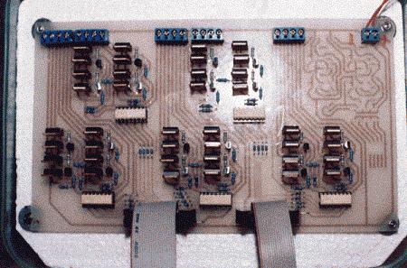
Therefore I had to build my own H-Bridge circuit from simple components that I could find in our market such as transistors and resistors. A picture of my home-built motor driver is shown at the top of this page. It is able to handle up to 12 motors simultaneously.
An H-Bridge can be built from switches (such as relays) for producing on/off outputs or continuous amplifiers such as transistors for producing both continuous and on/off outputs. Since commands sent to the amplifier are in form of PWM, we only need the switching case. We chose a transistor-based H-Bridge because of its lower cost, smaller size, higher speed and sensitivity.
There are two common types of transistors, namely FET and BJT. FET transistors make less heat and have a higher power rating than BJTs. Nonetheless, I used BJTs in because of my little budget and their lower cost.
This board is connected to control board using optical isolator. This is to save control board from any possible damage caused by high currents in amplifier side. Switching frequency of optical isolator must be less than PWM's, otherwise pulses are distorted when passing through isolator.
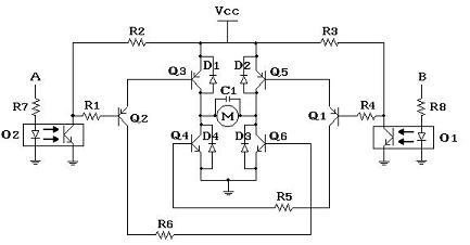
Below the schematic of our H-Bridge design is shown. This schematic is duplicated on the board as many as required, 12 times in our case.