Controlling LEDs from MATLAB
28 December 2010
As part of the GelSight project, I have been exploring options for controlling LEDs and cameras from MATLAB. I came across the Arduino platform and was able to develop a working system with almost no prior electronics experience. This post documents some of my initial experiments with controlling LEDs from MATLAB using an Arduino board.
Parts
Here is a list of the different components used in this post:
- sparkfun.com: Arduino Uno board, Jumper wires, breadboard
- oznium.com: Prewired Surface Mount LEDs, 12V AC Adapter, Junction box
- digikey.com: 1K Ohm resistors (P1.0KBACT-ND), TIP120 transistor (TIP120-ND), 3 to 8 decoder (497-1799-5-ND)
Single LED
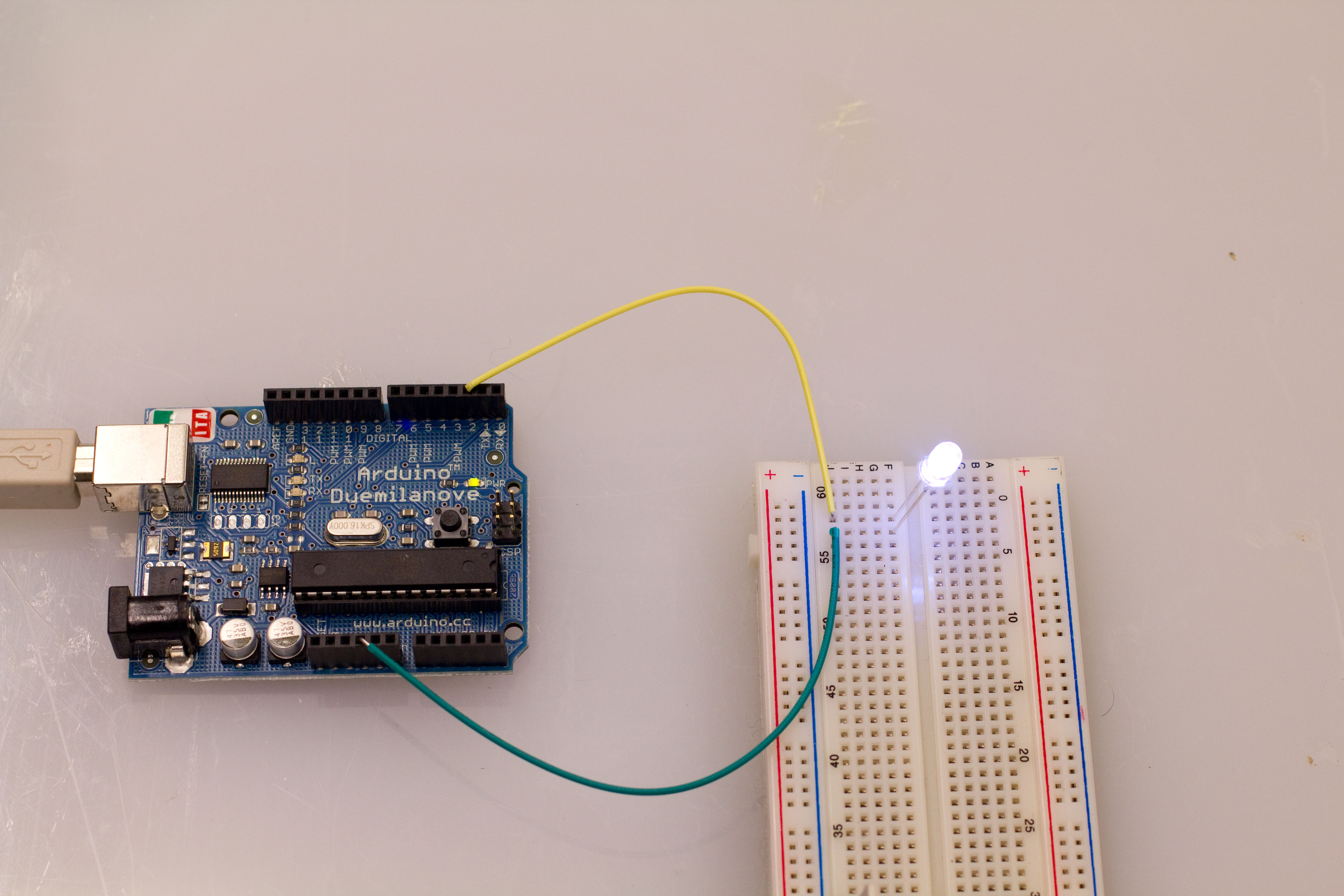
This is my implementation of the blink example from the Arudino tutorial. I won’t provide too much detail about this setup since it’s already described in the original tutorial.
Click here for a high-resolution image of the setup. The corresponding code for this example is:
int ledPin =  2;
int lighton = 500;
int transition = 500;

// The setup() method runs once, when the program starts
void setup()   {
  // initialize the digital pin as an output:
  pinMode(ledPin, OUTPUT);
}

// turn an LED on then off after 'ms' milliseconds
void controlLED(int pin, int ms)
{
  digitalWrite(pin, HIGH);
  delay(ms);
  digitalWrite(pin, LOW);
}

// the loop() method runs over and over again,
// as long as the Arduino has power
void loop()
{
  controlLED(ledPin, lighton);

  // wait between blinks
  delay(transition);
}
Single Prewired 12V LED
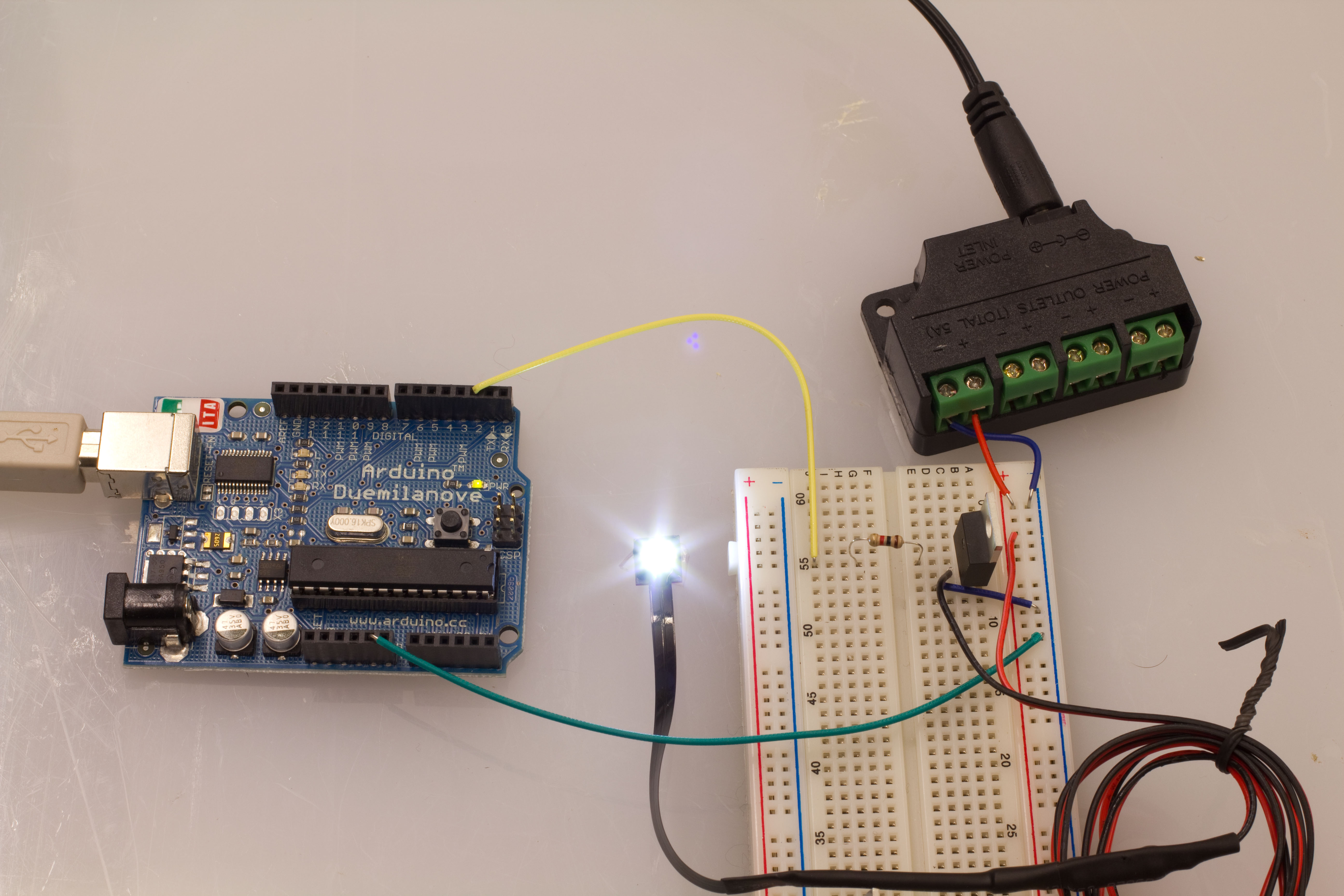
To save time in configuring and testing LED setups, I often work with prewired LEDs. This way, I can typically get something running without any soldering. I buy my LEDs from oznium.com, a company that specializes in LED lighting for cars. Since these LEDs are often configured for 12 volts, I need to provide an external power source.
In this design, I provide 12 volts to the LED and use a transistor to switch it on and off:
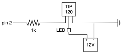
The code is the same as the previous example. To see a high-resolution image of the setup, click here.
Five LEDs
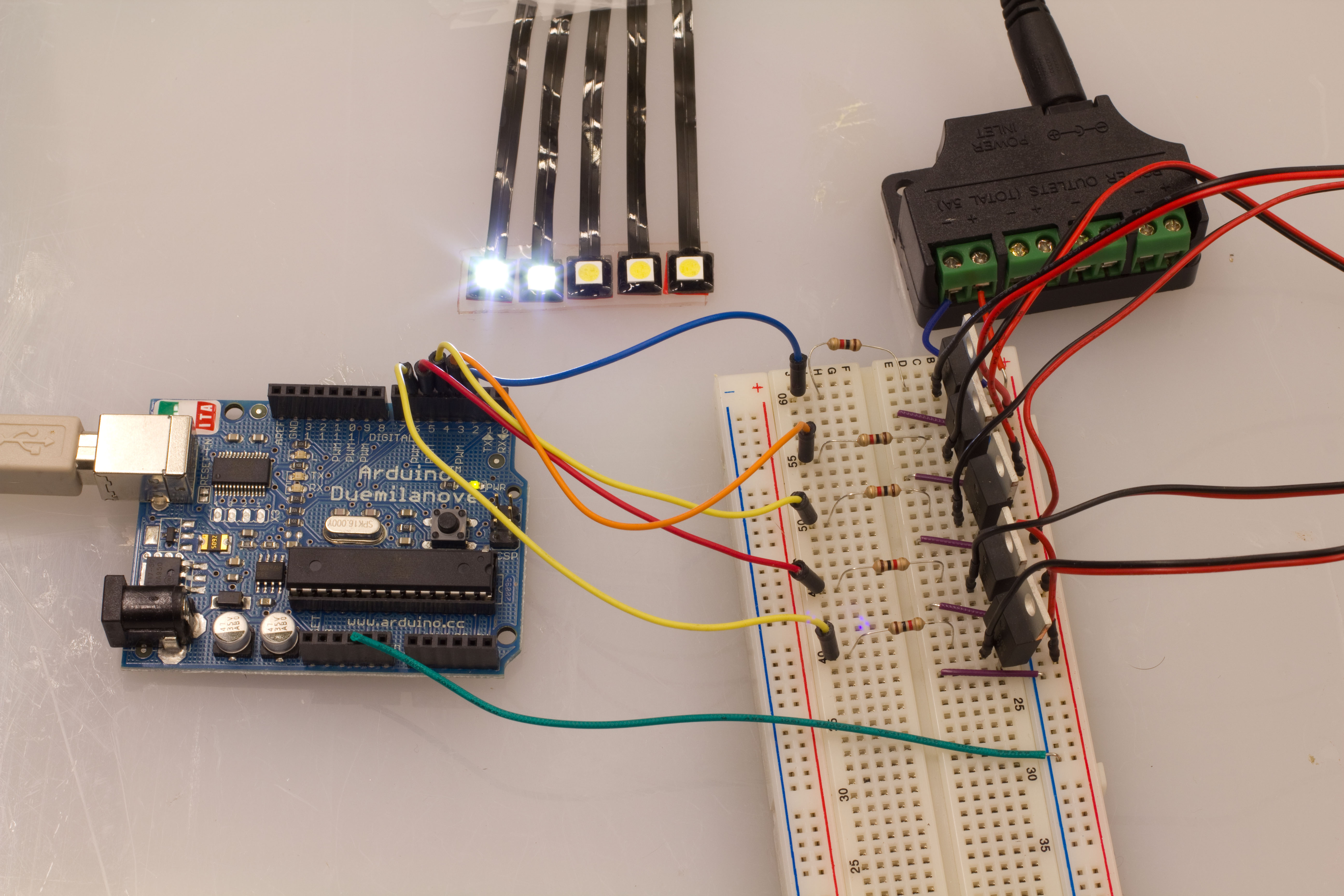
The setup of a single LED can be replicated to control multiple LEDs. Here is an example with five LEDs.
Click here for a high-resolution image of the five LED setup. The corresponding code for this example is:
int ledPins[5] =  {2, 3, 4, 5, 6};
int lighton = 500;
int transition = 30;

void setup()   {
  // initialize the digital pin as an output:
  int i;
  for (i = 0; i < 5; i = i + 1) {
    pinMode(ledPins[i], OUTPUT);
  }
}

void controlLED(int pin, int ms)
{
  digitalWrite(pin, HIGH);
  delay(ms);
  digitalWrite(pin, LOW);
}

void loop()
{
  int i;
  for (i = 0; i < 5; i = i + 1) {
    controlLED(ledPins[i], lighton);
    delay(transition);                  // wait for a second
  }
}
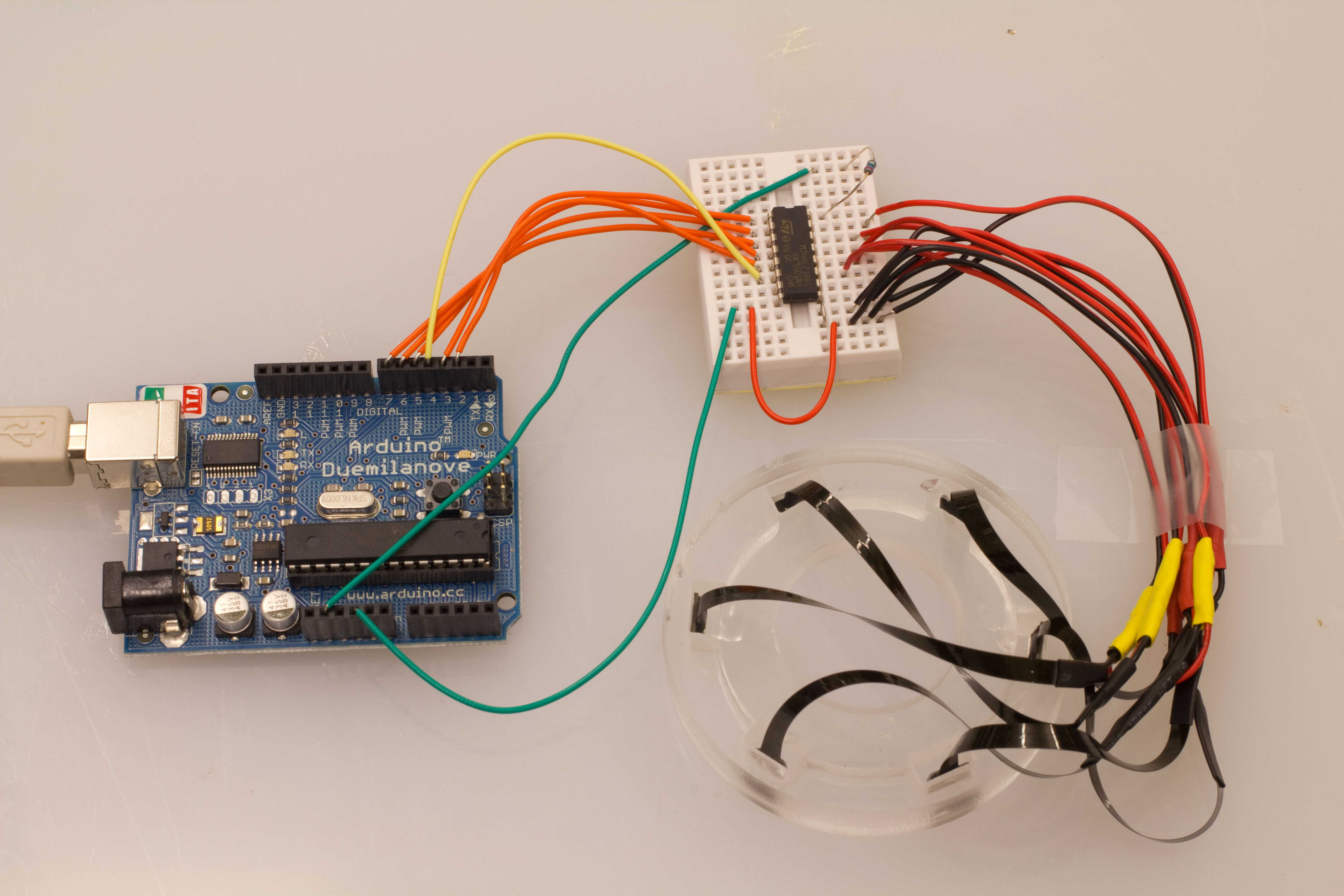
Six LEDs using decoder chip
The previous example does not scale well to more than a few LEDs since it uses an output pin and a resistor per LED. A better solution is to use a decoder chip, such as a 3 to 8 decoder (part 497-1799-5-ND from digikey). With this chip, you set the three data pins high or low according to the binary representation of the output pin you want to control. In this way, you control a set of LEDs using only a logarithmic number of data pins, implying that the solution will scale well to lots of LEDs.
Click here for a high-resolution image of the six LED setup using a decoder chip. I determined how to set the pins by reading the manual. The corresponding code for this example is:
int dataPins[3] = {5, 6, 7};
int controlPins[3] = {2, 3, 4};

int lighton = 500;
int transition = 30;

void setup()   {
  // initialize the digital pin as an output:
  int i;
  for (i = 0; i < 3; i = i + 1) {
    pinMode(dataPins[i], OUTPUT);
  }
  for (i = 0; i < 2; i = i + 1) {
    pinMode(controlPins[i], OUTPUT);
  }

  // set control[0] to LOW
  digitalWrite(controlPins[0], LOW);
  digitalWrite(controlPins[1], LOW);
}

void blinkLED(int val, int ms)
{
  digitalWrite(controlPins[2], LOW);
  int temp = 1;
  for (int i = 0; i < 3; i = i + 1) {
    if (temp & val) {
      digitalWrite(dataPins[i], HIGH);
    }
    else {
      digitalWrite(dataPins[i], LOW);
    }
    temp = temp << 1;
  }

  digitalWrite(controlPins[2], HIGH);
  delay(ms);
  digitalWrite(controlPins[2], LOW);
}

void loop()
{
  int i;
  for (i = 0; i < 6; i = i + 1) {
    blinkLED(i, lighton);
    delay(transition);                  // wait for a second
  }
}
Controlling LEDs from MATLAB
Now that the LEDs work, we can set up a mechanism for controlling them from MATLAB. I use the serial port on the Arduino board to listen for commands from MATLAB. For example, here is some code that controls a set of LEDs that are configured like the five LED example from above (i.e., no decoder chip). The board listens for single characters over the serial port and sets the LEDs accordingly.
int ledPins[6] =  {2, 3, 4, 5, 6, 7};

int lighton = 100;
int transition = 30;
int trigwait = 300;
int snapdelay = 100;

void setup()   {
  Serial.begin(9600);
  // initialize the digital pin as an output:
  int i;
  for (i = 0; i < 6; i = i + 1) {
    pinMode(ledPins[i], OUTPUT);
  }
}

void pulseLED(int pin, int ms)
{
  digitalWrite(pin, HIGH);
  delay(ms);
  digitalWrite(pin, LOW);
}


void loop() {

  int lednum;
  if (Serial.available() > 0) {
    int inByte = Serial.read();

        // Pulse LEDs
    if (inByte >= 'a' && inByte <= 'f') {
      lednum =  (int)inByte - 'a';
      pulseLED(ledPins[lednum], lighton);
      delay(transition);
    }

        // Turn LEDs on
    if (inByte >= 'g' && inByte <= 'l') {
      lednum =  (int)inByte - 'g';
      digitalWrite(ledPins[lednum], HIGH);
    }

        // Turn LEDs off
    if (inByte >= 'm' && inByte <= 'r') {
      lednum =  (int)inByte - 'm';
      digitalWrite(ledPins[lednum], LOW);
    }
  }

}
From within MATLAB, I open a serial connection and write characters using
fopen and fprintf. The following code will cause the first LED to blink. Note that the string that specifies the serial port will vary depending on your machine and Arduino board; it is found in the Tools->Serial Port menu of the Arduino software.
>> serialobj = serial('/dev/cu.usbserial-A700eCx6');
>> fopen(serialobj);
>> lnum = 1;
>> fprintf(serialobj, 'a' + (lnum-1));
>> fclose(serialobj);
Conclusions
This post described a simple method for controlling sets of LEDs from MATLAB. I have also used similar techniques to control a Canon Rebel digital camera from MATLAB using a stereo cable (part CP-2203-ND from digikey). By controlling both the camera and lights from MATLAB, I have been able to gather lots in a systematic way.