PicasoBot - a sketching robot
PicasoBot is a drawing robot. A user can draw a picture on a tablet computer, and PicasoBot will physically sketch it. Designed, machined, wired, and programmed from the ground up, PicasoBot was my final project for 6.115 (Microcomputer Laboratory).
Mechanical Design
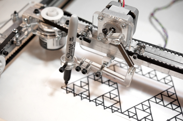
PicasoBot uses a 3-axis CNC mechanism design. The X and Y axes move the drawing head, and a third axis pushes a pen or marker against the paper with varying degrees of force. The X and Y axes are actuated using bipolar stepper motors with 0.9 degrees per step resolution connected. This theoretically allows for sub millimeter resolution, but in practice back lash in the pen mount mechanism decreases this accuracy. These steppers are connected to a timing belt pull cart, similar to the mechanism used in printers, laser cutters, and many other CNC devices. Bearings slide in a milled groove along the aluminum rail. Many pieces of the design were fabricated out of clear acrylic on a laser cutter.
The drawing head is also controller with a bipolar stepper motor connected in series through a spring to the marker. This is geometrically designed such that the spring will be in its linear region as the pen touches the paper, thereby roughly allowing linear force control of the pen against the paper with minimal complexity.
Electronics Architecture
PicasoBot uses an 8051 microcontroller to control its three stepper motors. A port multiplexing chip is connected to the 8051, and expands number of digital I/O pins available. Twelve digital I/O lines are used to control the steppers. Three push-pull driver chips with flyback diodes are connected to these digital I/O lines to drive the stepper motors, which operate at 12V. Encoders were originally incorporated into the mechanical design, but were not found to be needed extensively due to the strength of the stepper motors (though there is some “drift” sometimes).
Software
The core PicasoBot firmware is programmed in 8051 assembly language (6.115 is after all a microcontrollers class!). There is also a small PIC chip programmed in C that controls an LED status indicator. The 8051 is an 8-bit microcontroller, but many computations required 16 bit computations in order to have enough resolution to control the stepper motors. This presented some interesting technical challenges while programming PicasoBot’s firmware.
A user first draws a sketch on a computer, using a Java program that records the sketch strokes geometrically. This program also allows a user to re-import a previously drawn sketch. Once ready, this sketch is downloaded via serial to the 8051 where it is stored in RAM. The firmware on PicasoBot then draws each of the geometric primitives by controlling the stepper motors.
Pictures and Videos
Here is a video of the robot in action:
The following image was drawn by Frank Yaul ‘11 on a tablet. PicasoBot then rendered it on real paper with a sharpie:


