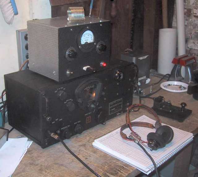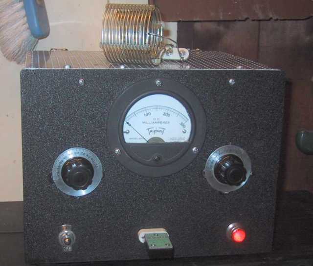

The transmitter here is a homebrew "one tube" crystal oscillator. It uses a 6146 in a Grid-Plate circuit and puts out about 15 watts running straight thru on 80 or 40 meters, or doubling on 40 or 20 meters. The power supply provides 350 v. under load.
The output circuit is a parallel-fed tuned link arrangement with plug in coils. One coil covers 80 and 40, the other 30 and 20.
It works best when loaded to about 75 ma, and using FT-243 crystals, it is essentially chirpless on 80 and 40, and has "light" chirp on 20 (where it is doubling the xtal).


I acquired the chassis / panel / variable capacitor / knobs assembly at a swap meet (it was an antenna tuner), and used it as a foundation for building the transmitter ( which explains the extra holes in the chassis). The RF components are somewhat larger than they need to be...

I'm not very proud of the 5Y3 mounted under the chassis (ok, it's really a two tube rig) , but the specs say it is ok to mount the tube horizontally.
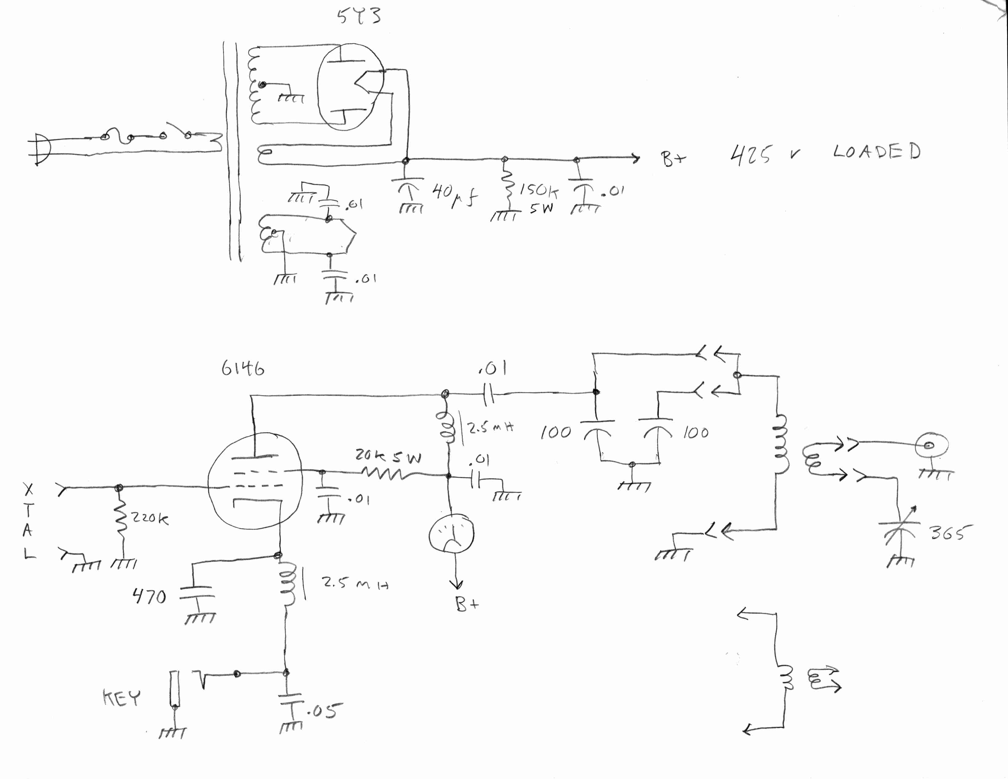
Here is the schematic (and, oops, the two 100pf caps in the output network are a ganged variable cap):

Coil data:
I made two plug in coils. One covers 80 and 40 meters, the second covers 30 and 20 meters. For the primaries, both coils use 2 1/4 inch dia 8 tpi stock, and the secondaries use 1 1/2 inch dia 10 tpi stock. The primaries have 15 and 5 turns for the 80/40 and 30/20 coils respectively. The secondaries have 8 and 2 turns respectively.
The 80 / 40 meter coil connects to both 100 pf sections in parallel, while the other coil only connects to one section.