
|
| http://people.csail.mit.edu/jaffer/SimRoof/Convection/Plate |
Isothermal Plate Construction |
These photographs document the construction of the convection-measuring plate in 2015.
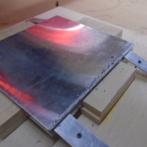
This photo shows the square MIC-6 aluminum slab fixtured in the numerically-controlled milling machine. Although difficult (gummy) to machine, MIC-6 aluminum was chosen for its low emissivity, 0.04.
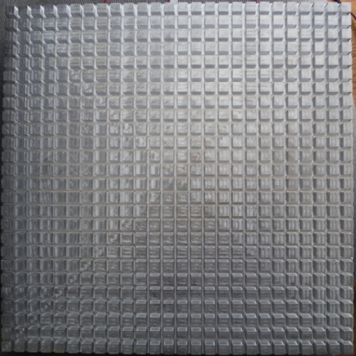
Pictured is the 30 cm × 30 cm plate for measuring
the convection from its rough surface. The surface is composed of
8.28 mm × 8.28 mm × 6 mm posts spaced on
11.7 mm centers. The area of the top of each post is
0.722 cm2, 53% of the 1.37 cm2 cell.
Its root-mean-squared height of roughness is 3 mm.
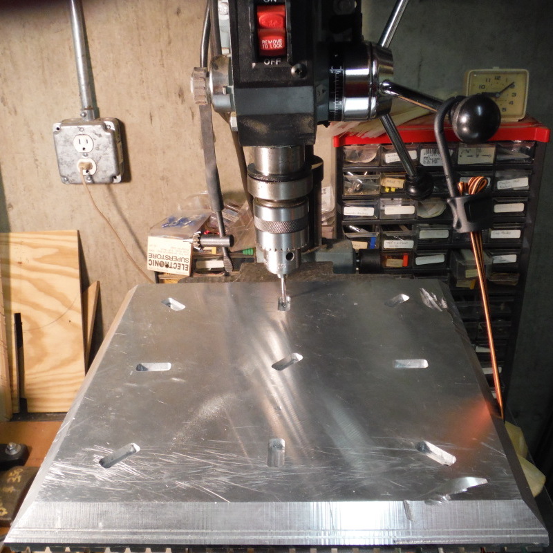
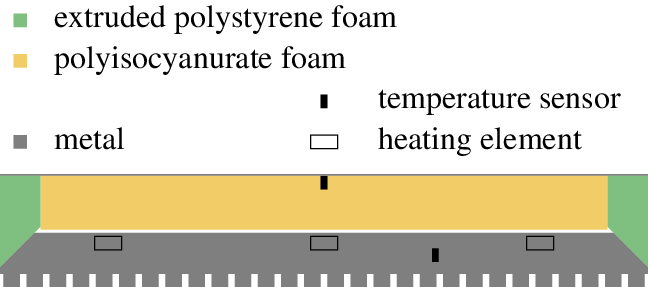
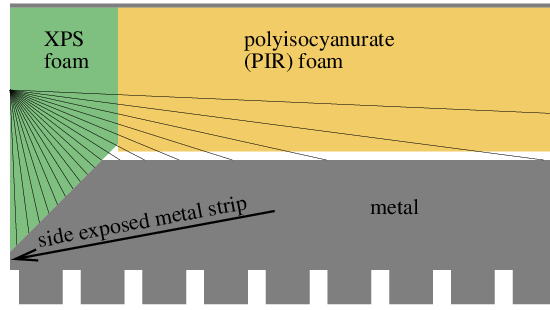
The back surface of the plate is beveled in order to reduce heat
transfer through the sides of the assembly.
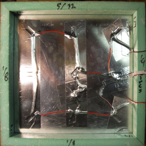
It has 9 electric heating elements, which are recessed so that they
don't come into contact with the thermal insulation covering the
back side.
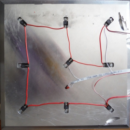
This view shows the heating elements (TO-220 resistors) in their cavities cut into the back of the plate. The gray ribbon cable connects to an electronic sensor in a blind hole to measure the plate's temperature.
MIC-6 aluminum's bulk thermal conductivity is 142 W/(K⋅m).
The plate's thermal conductance over its full thickness
(2.2 cm) is 600 W/K. That is, 1K of temperature drop will
result from every 600 W of heat flow. The thermal conductance
from the bisecting plane to the edge (15 cm) is 6.25 W/K.
As long as heaters are distributed well over the backside, the
thermal resistance of the plate itself can be ignored. Aluminum's
specific heat is 897 J/(kg⋅K), its density
2710 kg/m3, yielding a thermal capacity of
4.69 kJ/K for the slab. 50 W will heat the slab at the
rate of 1 K per 78 s.
The voids and recesses are covered with aluminum tape. The extruded
polystyrene foam wedges are glued to the bevel.
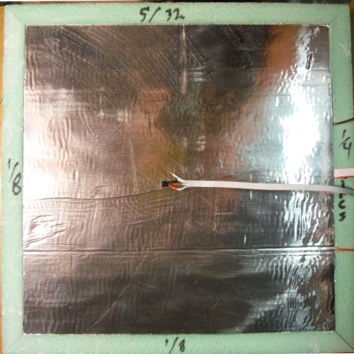
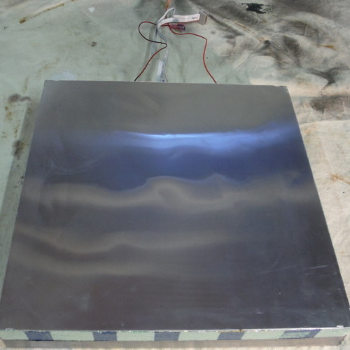
This photo shows the back with a square of polyisocyanurate foam
filling the space ringed by the EPS foam wedges. The gray wires
connect to a temperature sensor. The temperature sensor in contact
with the foil facing makes it possible to measure the heat
conduction through the foam.
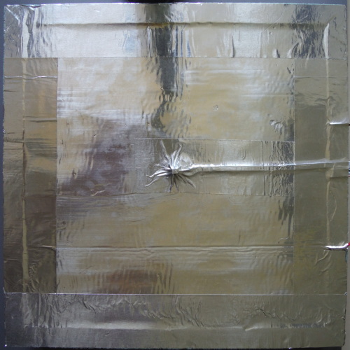
Aluminum tape extends the foil to the entire back plane.
Here is the back side of the plate ready to have the 0.65 mm
sheet of aluminum glued to it. Notches have been cut (using the
"nibbler" on the sheet) near the sheet corners to catch the wires
which will suspend it with the rough face upward.
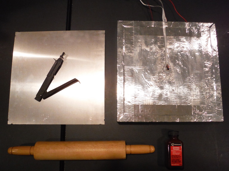
Gluing completed.

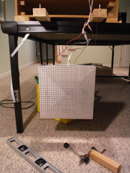
Here the rough surface of the plate is facing up in the wind tunnel.
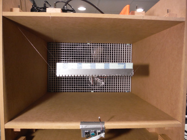
The plate is suspended from four 0.38 mm-diameter lengths of steel piano wire terminated at eight zither tuning pins in wooden blocks above the test chamber. The wire is sheathed by close-fitting Teflon tubing where it would contact the plate.
There is a strip of duct-tape covering the metal edge between the
insulation and the machined surface.
The ambient sensor board (temperature, pressure, humidity)
can be seen at the bottom edge of the tunnel.
Horizontal flow to the plate inside the test chamber is obstructed by the test chamber walls in the vertical orientation. Measurements of natural convection from the vertical plate were made by suspending the plate outside of the wind-tunnel.
|
I am a guest and not a member of the MIT Computer Science and Artificial Intelligence Laboratory.
My actions and comments do not reflect in any way on MIT. | ||||||||
| SimRoof | ||||||||
| agj@alum.mit.edu | Blog | Go Figure! | ||||||