
|
| http://people.csail.mit.edu/jaffer/convect/instructions |
Operating instructions |

The photograph shows the controls and cabling for making convection measurements in the wind-tunnel.
The two short cables from yellow connectors at top left-center connect with two Lenovo 20 V (80 W) power supplies. The right cable powers all the electronics; the left cable is used only for heating the plate. The two green LEDs (one hidden by a ribbon cable) indicate that the power is on.
The 18 AWG tinned and copper wires between the large black heat-sink and the power cables heats the plate. Its connections must not be reversed.
At the lower left are two mini-USB type B connectors. The leftmost connector is for monitoring or downloading the the most recent run. The other USB connector is used only for loading new firmware into the microprocessor.
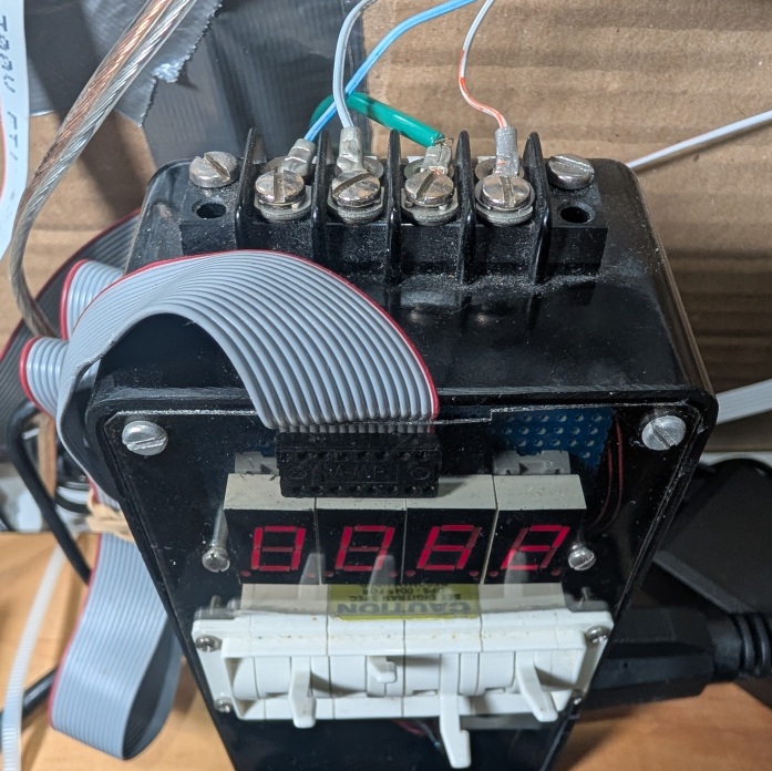 The 16-wire ribbon cable connecting from the circuit board to the
black box reads the four decade switches and controls the display of
fan rotations per minute. The photograph to the right shows the
four wires with fork crimps terminating in a barrier strip on top of
the black box. The green wire connects to the third-prong safety
ground. The other wires sense the AC phase and control the
solid-state relay gating power to the fan. Those wires are part of
the 26-wire ribbon cable plugged into a blue socket on the right
side of the board.
The 16-wire ribbon cable connecting from the circuit board to the
black box reads the four decade switches and controls the display of
fan rotations per minute. The photograph to the right shows the
four wires with fork crimps terminating in a barrier strip on top of
the black box. The green wire connects to the third-prong safety
ground. The other wires sense the AC phase and control the
solid-state relay gating power to the fan. Those wires are part of
the 26-wire ribbon cable plugged into a blue socket on the right
side of the board.
The other wires in the 26-wire ribbon cable connect to sensors in
the plate and the ambient board, and also the IR LED and IR
photo-transistor mounted on the fan's wire cage.
There are blue and black momentary-contact switches on the green
printed circuit board. The black button resets the processor; it
should be pressed before reconnecting the USB cable after
disconnecting it from a computer. To minimize electrical noise, the
USB cable should not be connected to a computer during a measurement
run.
The white circle printed on the green circuit board is ringed by eight LEDs, diametrically opposed pairs of red, green, yellow, and blue. The dynamic patterns of these LEDs indicate the current state of the apparatus.
The idle pattern flashes seven of the LEDs in a 2-2-2-1 sequence pointing to the blue button. After a run has completed, the pattern flashes seven of the LEDs in a 2-2-2-1 sequence pointing away from the blue button.
./monitor.scm
streaming from "/dev/ttyACM0"
fetching data
20220504T233725 -> ..20220504T233744
     date-time      reps drive   power  ambient plate   back    drvdisp  PFET   RH      AP      fan
2022-05-04T23:37:44Z 16  0.000W  0.000W 18.79C  18.75C  18.76C   0.038W  0.20C  49.1%   100989Pa  200r/min
2022-05-04T23:37:45Z 16  0.000W  0.000W 18.72C  18.71C  18.75C   0.062W  0.23C  49.0%   100972Pa  200r/min
2022-05-04T23:37:46Z 16  0.000W  0.000W 18.79C  18.71C  18.73C   0.047W  0.21C  49.1%   100986Pa  200r/min
2022-05-04T23:37:47Z 16  0.000W  0.000W 18.73C  18.75C  18.80C   0.060W  0.24C  48.8%   100995Pa  201r/min
2022-05-04T23:37:48Z 16  0.000W  0.000W 18.78C  18.61C  18.77C   0.042W  0.24C  49.1%   100971Pa  199r/min
These readings indicate that the plate was at room temperature and the fan was spinning at 200 rotations per minute.
| column | description |
|---|---|
| date-time | UTC date and time (ISO-8601) |
| reps | count of 12 bit conversions per reading |
| drive | heater power target |
| power | heater power measured |
| ambient | ambient temperature |
| plate | rough surface temperature |
| back | plate assembly back temperature |
| drvdisp | driver circuit power dissipation |
| PFET | power-FET temperature (intermittent) |
| RH | relative humidity |
| AP | atmospheric pressure |
| fan | fan rotation rate |
To stop monitoring, press the blue button for 3 seconds. The raw readings are stored in a file named with the ISO-8601 encoded starting time with suffix ".tsv" (20220504T233744.tsv) in your current directory.
Invoking "monitor.scm 20220504T233744.tsv" will print out the readings again.
The six-wire plate suspension has thus far survived rotations between horizontal and vertical orientations. Shifting of the plate alternated with tightening and loosening of wires may be needed after changing orientations in order to maintain its position in the center of the wind-tunnel test chamber. It was quite difficult to attach the suspension; if the plate is ever disconnected, 45° holes should be drilled through 4 corners, which should make threading the wires much easier.
The open intake wind-tunnel is a simple design, but is prone to free-stream turbulence. The horizontal wind-tunnel intake must project beyond the edge of the table. Remove all objects within a meter of the intake; many runs were spoiled before it was realized that this was the cause.
The outflow from the fan is quite turbulent at high speeds. The folded mass of garden netting held against the fan housing by a wire grill and Bungee cords smooths this flow so that vortexes are less likely to be drawn around to the open intake. The successful horizontal runs were made in a large room with 3 m of clearance behind the netting. High speed runs on the wind-tunnel in the vertical orientations were problematical because it had smaller clearances than in the horizontal orientation in the large room. Fortunately, the aiding and opposing transitions occurred at Re<20000.
 The wind-tunnel can measure from 305 mm square plates or 12 mm
diameter thermistor disks. This is controlled by the bank of eight
switches shown in the photograph to the right. Switches 2 through 8
should be OFF for the square plate and ON for the thermistor disk as
shown in the image to the right.
The wind-tunnel can measure from 305 mm square plates or 12 mm
diameter thermistor disks. This is controlled by the bank of eight
switches shown in the photograph to the right. Switches 2 through 8
should be OFF for the square plate and ON for the thermistor disk as
shown in the image to the right.
The fan bearings have more friction when the wind-tunnel is vertically oriented (and the fan is horizontal). In order for the firmware phase-locked loop to run stably below 60.r/min, swatch 1 should be ON for vertical and nearly vertical wind-tunnel orientations, and OFF otherwise, as shown in the image.
When the wind-tunnel is vertical, run the low-speed tests first. As the fan bearings warm, the PLL can lock at half of the desired low speed.
Due to the variability of thermistor disk parameters, the firmware is specific to one disk. To rebuild the firmware execute:
"make -f Firmware.Makefile all"
from the "convect" directory. To program the microprocessor, move the USB cable to the center USB connector on the green board, connect to the computer and execute
"make -f Firmware.Makefile program"
from the "convect" directory.
The fan speed is set using the 4 decimal switches below the four digit rotations-per-minute display. The rightmost three switches encode the speed between 0 and 999. The leftmost switch encodes the measurement mode, and whether to add 1000 to the speed indicated by the other three switches. The measurement mode encoding differs between thermistor disks and square plates:
| switch | r/min | square plate ΔT | disk measurement mode |
|---|---|---|---|
| 0 | +0 | 0 K | voltage and current calibration with 100.0.Ohm resistor replacing the disk fixture |
| 1 | +0 | 5 K | disk temperature calibration |
| 2 | +0 | 10 K | measurement |
| 3 | +0 | 15 K | |
| 4 | +0 | 20 K | |
| 5 | +1000 | 0 K | |
| 6 | +1000 | 5 K | |
| 7 | +1000 | 10 K | measurement |
| 8 | +1000 | 15 K | |
| 9 | +1000 | 20 K |
Within 6 seconds, the rotations-per-minute display should show values near to the speed selected by the switches between 40 r/min and 1300 r/min. If your line voltage is less than 117 V, the upper speed limit may be less.
Check that the USB cable is not connected to a computer, the mode and speed are set as desired, and the LEDs are showing the idle pattern. Then press and release the blue button; this will stop the fan and start the measurement run.
The run can be terminated early by pressing the blue button for 3 seconds. Pressing the black button (reset) also terminates the run, but the last row of data may be corrupted when downloaded.
Setting the switches as "1000" selects "calibration" mode. The two LM37 temperature sensors which are connected to the ribbon cable inside the test chamber are clamped to opposite sides of the disk by a calibration fixture (and clothespins) which snaps into the disk holder. The firware increases temperature in six steps at 100 s intervals; then steps temperature down. This process takes 1400 s (23 min, 20 s). The two LM37 temperature sensors are not used in other modes.
In "measurement" mode, the firmware increases the disk temperature in six steps at 100 s intervals. The fan is off during the first 100 s, on for the next 200 s, and on for the last 75 s of each of the remaining four 100 s intervals. Measurement runs take 700 s (11 min 40 s).
The red LEDs will alternately flash while the disk is heating; the blue LEDs will alternately flash while the disk is cooling.
The data can be downloaded from either the idle state or the run-complete state (2-2-2-2). If a computer had been attached to USB before the run, press the black button to reset to the idle state.
The raw data files do not capture the orientation of the plate and wind-tunnel. That information is manually entered into "convect/1mm/key.txt" and the "General Lab.Book" kept near the wind-tunnel. Each line has the ISO-8601 date.tsv, "th = " the plate angle between -90 (upward facing) an +90 (downward facing), "DT = " the heat setting (0K, 5K, 10K, 15K, or 20K), and the rotation rate set by the switches followed by ".r/min". If "th = +0", the angle of the flow versus vertical rising is entered as a second number. Vertical aiding is "th = +0 0"; vertical opposing is "th = +0 180"; vertical with horizontal flow is "th = +0 90". Any lines beginning with space are comments.
|
I am a guest and not a member of the MIT Computer Science and Artificial Intelligence Laboratory.
My actions and comments do not reflect in any way on
MIT. | ||
| Convection Articles | SimRoof | |
| agj @ alum.mit.edu | Go Figure! | |