
|
| http://people.csail.mit.edu/jaffer/convect/wind-tunnel |
Wind-tunnel construction |
After several years of reliable operation, inconsistent convection measurements led to suspicions that a cowling seam had opened. This was confirmed, leading to reassembly of the wind-tunnel cowling.

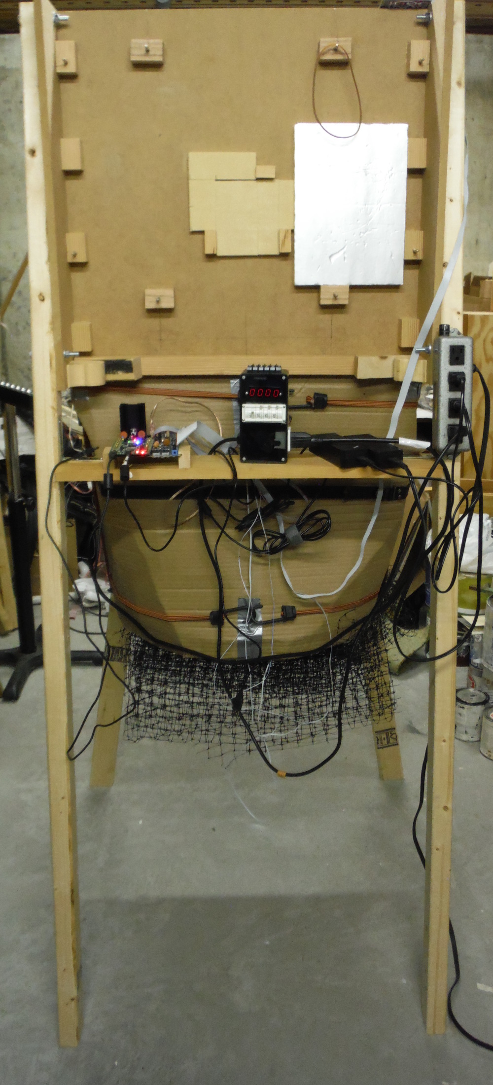
Shown is the wind-tunnel chassis with fan (blowing from right to left) and test chamber. The white plastic grill is to disrupt vortexes from the intake side of the fan from entering the test chamber.
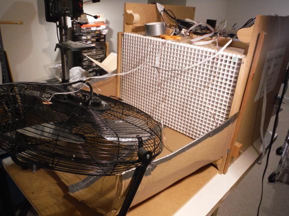
The fan is swiveled to horizontal so that the lower half of cardboard cowling can be inserted.
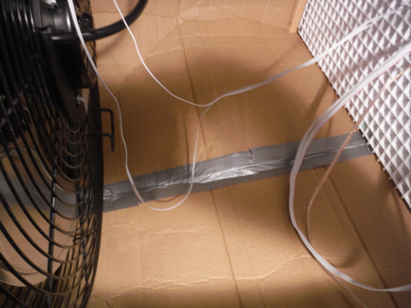
The bottom seam is duck-taped both inside and outside.
Third quarter of cowling added.
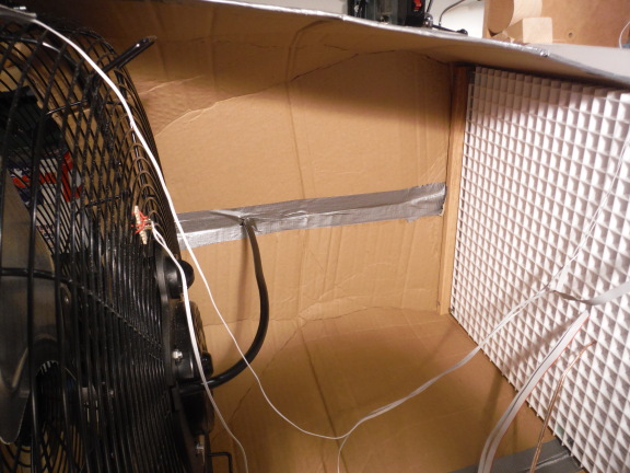
This side seam is duck-taped both inside and outside.
The small tan rectangle on the fan cage is the infrared LED to detect the passing fan blades.
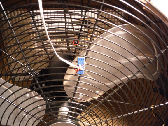
The small blue board holds the photo-transistor which detects the infrared beam.

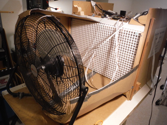
The fourth quarter of the cowling was added, its seams sealed, and end flaps inserted into the fan's wire cage. A belt secures the cowling pieces to the fan cage.

The fan blows through folded plastic mesh in order to break up the vortexes which are pulled around the outside of the tunnel and sucked into its open intake when the fan speed is near maximum.
Wires connecting to the infrared LED and the plate thread through the top cowling seam.
Wedges press the horizontal white bar to seal the cowling cardboard against the test chamber housing. A similar bar seals the lower cowling panel. Smaller bars screwed to the test chamber sides seal the cowling sides.
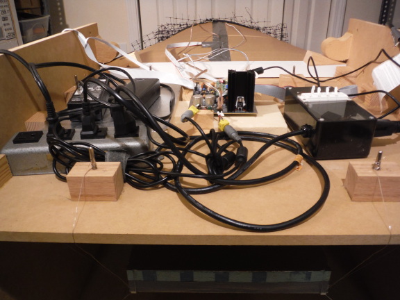
The top of the wind-tunnel holds the measurement and control electronics when the tunnel is horizontal.
Here the tunnel is oriented vertically with the fan pulling air downward in order to measure vertical opposing mixed convection. Clearance below and around the tunnel is not sufficient to prevent vortexes from getting sucked around and into the open intake; the convection measurements when Re>104 do not stay within their estimated measurement uncertainty bounds.
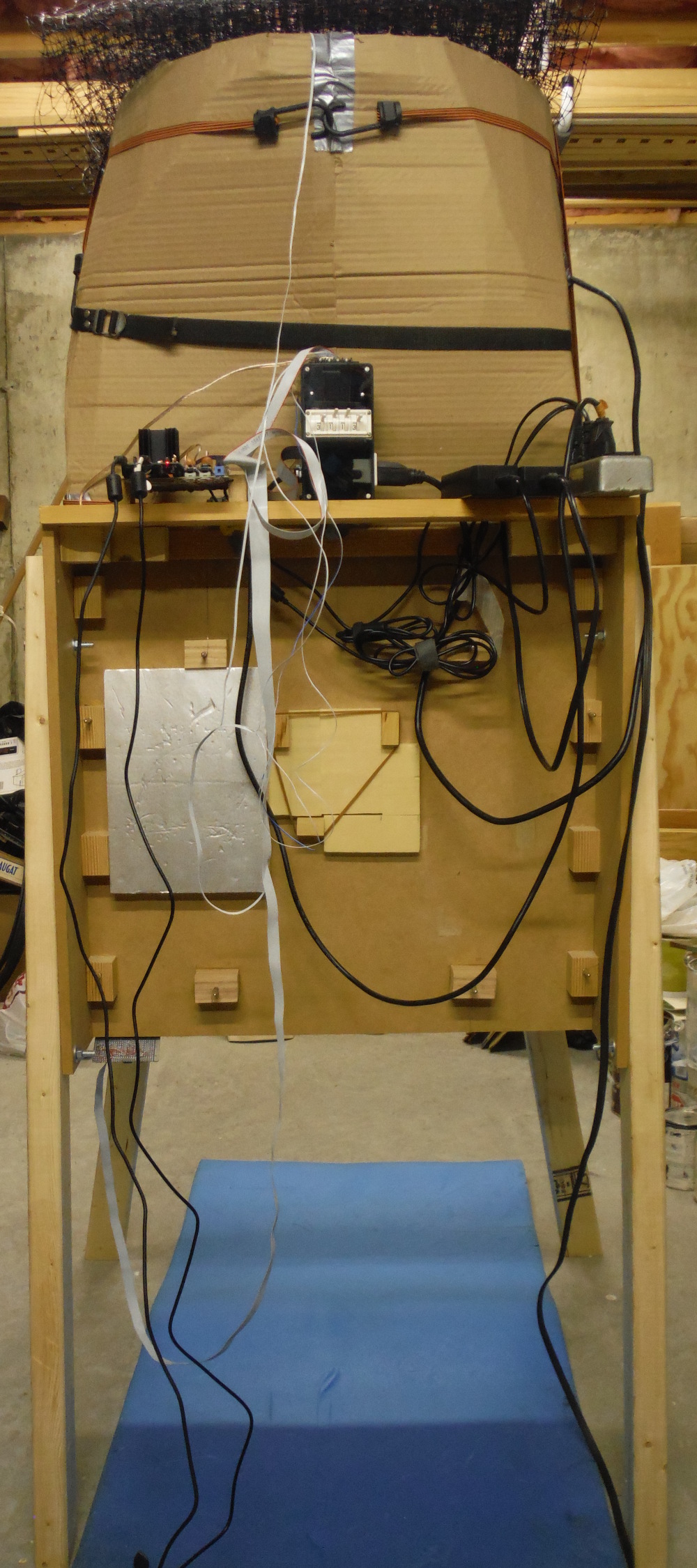
Here the tunnel is oriented vertically with the fan pulling air upward in order to measure vertical aiding mixed convection. It also suffers from the insufficient clearance problem.
The blue foam pad on the floor allowed me to adjust the plate suspension while not laying directly on the hard concrete floor.
|
I am a guest and not a member of the MIT Computer Science and Artificial Intelligence Laboratory.
My actions and comments do not reflect in any way on
MIT. | ||
| Convection Articles | SimRoof | |
| agj @ alum.mit.edu | Go Figure! | |