USB data logger project
This is a project I did at the end of my year at Cambridge (a 3rd year project). It's a two-person team project. I was working with Michael Birmingham. We were given a microcontroller, a circuit board, and an allowance of 10 pounds to somehow build an oscilloscope out of it. The hardest part was to get the communication protocal working. We had to design the circuit and write the software support around it. It was a very successful project, proven by the grades we got.
Introduction:
In this project, PIC 18F4550 is programmed to perform the function of an oscilloscope. Communication is set up between the computer and the PIC through USB, so that bulk data transfer mode is implemented. Analogue circuits are carefully designed so the user can select gain and offset on the computer screen and have the circuit perform the corresponding functions. Also software based calculations like FFT and cursor information can be displayed on the screen. It is also possible to copy and paste the plot to notepad directly.
Specification:
Hardware:
The hardware specification is shown in Table 1.
| Sampling frequency | 16kHz |
| Input frequency range | [2Hz-4kHz] |
| Input voltage range | [0V-5V] |
| Resolution | 9.78x 10^(-3)V |
| Gain | [0.1-100] |
Software:
The software specification of the oscilloscope is shown in Table 2.
| Display rate | 0.52Hz |
| Software functions | Single channel V(pk-pk), V(rms), frequency readings; User panel to set offset and gain; FFT calculation; Cursor display; Adjustable time base and voltage division; Sum and difference of signals from two channels; User panel to set the trigger source, level and sense; Auto set button to set appropriate time and voltage value for displaying signals. |
Hardware Design:
The goal of the hardware is to let the user select offset and gain from the computer user interface rather than twisting a little potentiometer. The design is shown in Graph 1 below. The computer enables the DAC and puts an 8-bit number onto the DAC data lines. The DAC output is sent to the "'+"' input of the first op-amp, providing an offset.
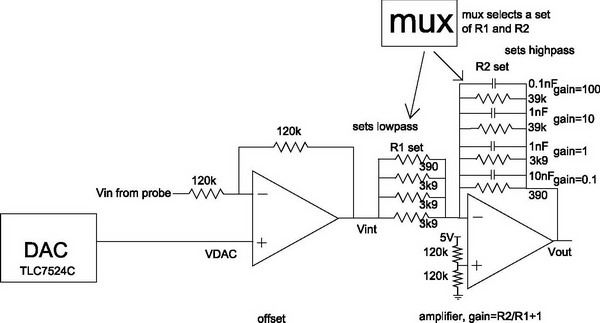
Graph 1: The hardware design
The second op-amp sets up the gain stage. There are four sets of resistors. A multiplexer is used to select one set only at a given time. The value of R_1 and R_2 sets up the gain provided that the "'+"' end is set at 2.5V. To mimic a real oscilloscope, we chose four options for the gain: 0.1, 1, 10, and 100. Capacitors that are parallel to the resistors right before the output stage set the high frequency cutoff of the circuit. The high frequency cutoff is set to be around 4kHz. This is lower than twice the fastest sampling frequency the circuit can perform, and thus eliminates aliasing problems. The schematic for the circuit is shown in Graph 2 below.
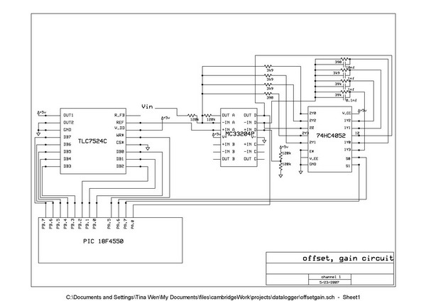
Graph 2: The schematic
It is to be noted that this is the circuit for one oscilloscope probe. Since we have two channels, the same circuit is supposed to be repeated twice. However, due to mistakes made in a long soldering session, one of our TLC7524Cs got destroyed. Luckily, we had another DAC called AD558. It works a little differently than TLC7524C. The output range for AD558 is [0-2.56V] other than [0-5V]. An additional times 2 multiplier op-amp is added after AD558. The circuit is shown in Graph 3 and schematic in Graph 4 below. The bill of material for ordering from Farnell is attached as Graph 5 below.
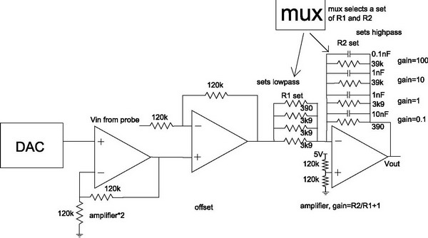
Graph 3: The circuit design with AD558
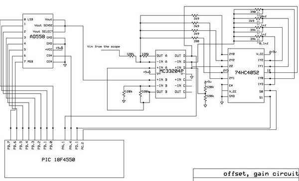
Graph 4: The schematic with AD558
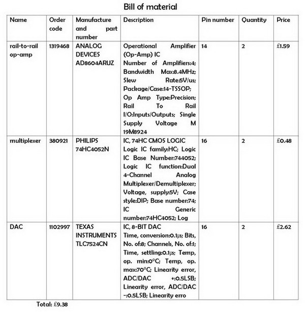
Graph 5: Bill of material
Communications Protocol:
We are using the 8-bit configuration for the ADC inside the microcontroller, because it offers a good tradeoff between conversation time and resolution.
Bulk data transfer mode is used for transferring data through USB. 256 bytes of data is sent every time through USB. (This is the upper limit we measured.) There are in total 40 lots of 256 bytes. Taking into account 40 bytes as command bytes, (for every 256 bytes, there is one command byte) we end up with 10,200 bytes of data, (256x40-40=10,200) of which we display 10,000. Data is transferred very efficiently this way.
The added communication commands are summarized below:
GET_ADC_COMMAND(command byte is 0xAA)
Software interface sends: {0xAA, channel number}(2 bytes)
Hardware returns: {0xAA, input data}(63, 64, 64 bytes)
READ_COMPARE(command byte is 0xBA)
Software interface sends: {0xBA, channel number}(2 bytes)
Hardware returns: {0xAA, CMCON register, input data}(3 bytes)
SET_PROPERTIES(command byte is 0xCA)
Software interface sends: {0xCA, compare value, channel 1 offset, channel 1 gain, channel 2 offset, channel 2 gain}(6 bytes)
Hardware returns: {0xAA}(1 byte)
Firmware Design:
A flow chart for firmware can be found in Graph 6 below.
Graph 6: The firmware design
The case GET_ADC_SEQUENCE in ServiceRequests function in the firmware implements the bulk transfer mode. The bulk data transfer request contains the first byte being the command byte, which should correspond to 0xAA. The second byte signifies the channel number. 0x01 is channel 1 and 0x02 is channel 2. The function ServiceRequests sends back the first byte as the command byte 0xAA, and the rest with conversion results contained in (1-63, 64-127, 127-191) bytes. This is done in three loops, each of which with 64 iterations.
A compare channel function is also implemented for triggering and calculations like V_max and V_min. This is done by using the comparator module in the microcontroller. First, in UserInit, we set bits [CM2:CM0] to be 110 to pick up the module four inputs multiplexed to two comparators. Then we initialize CVRCON to be 0xC8 to enable the comparator. Then we set bits [CVR2:CVR0] in the CVRCON register to take the value we want to compare to in function SetCompareReg. Finally in ReadCompareReg, CMCON.C1OUT has the result for channel 1, and CMCON.C2OUT has the result for channel 2.
This request has the command byte of 0xBA. The microcontroller reads the CMCON register value and appends it to the command byte, forming an outgoing data packet. Finally it reads the compare result, either CMCON.C1OUT or CMCON.C2OUT, depending on the channel number.
All the property changes are handled by one command SET_PROPERTIES. With the command byte 0xCA, the requester sends compare value, offset and gain for channel 1 and 2. Nothing other than the command byte gets returned. Following this command call, comparator comparing value, channel 1 offset and gain, channel 2 offset and gain are all updated.
Software Design:
Software uses multi-threading to refresh the screen and handle button callbacks simultaneously. There are two .c files, USBDriver.c and Oscilloscope.c. USBDriver.c has ReadChannel, CompareChannel, and SetProperties functions. It works hand-in-hand with firmware to accomplish interactions with the microcontroller. Oscilloscope.c handles processing of the read-in data. Some major functions in Oscilloscope.c are shown below:
main
It initializes USB, starts the display function, schedules threads for running the display function and dealing with button changes/callbacks. A flow diagram of this function is shown in Graph 7 below.
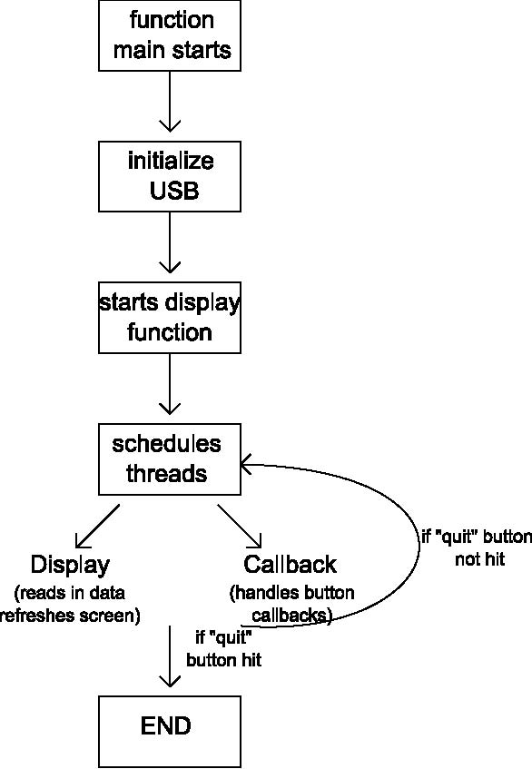
Graph 7: main flow chart
DisplayFunction
It waits for a trigger value first, then sits there constantly polling compare from the PIC until it gets the first datum with right level and sense. Then it reads both input channels from the PIC, and calculate things like min and max, frequency, sum and difference of the data, plots whichever channel selected on the display panel. This function does it forever until the quit button is hit. A flow diagram of this function is shown in Graph 8 below.
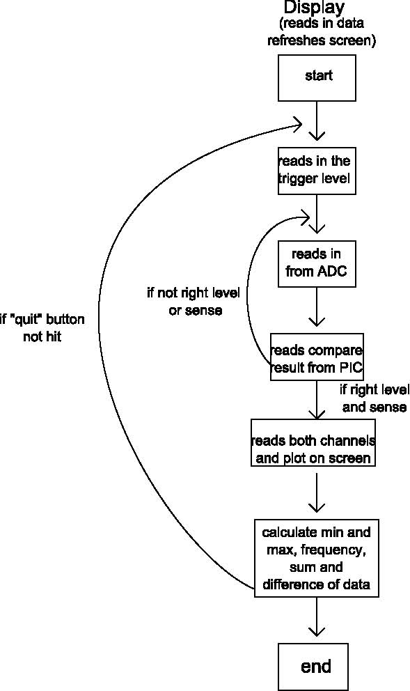
Graph 8: Display flow chart
min and max, frequency, peak-to-peak, and root-mean-square values are all calculated based on the 10,000 bulk of data we have. min and max values are calculated directly by a function provided by the CVI software called 1Dminmax after the array of data is passed to the function. Frequency is calculated first by determining the mid-point between min and max of the entire data set, then count the number of times there is a transition passing through this mid-point. Finally, this number is used to divide the time base to give the frequency. The peak-to-peak value is calculated by subtracting the min value from the max value. The root-mean-square is calculated by the taking the absolute value of the datapoint and divide it by 2^(1/2).
DisplayFFTFunction
It calculates FFT and displays it on the panel every second.
ShowChannelInformation
It reads in user's selection of information to show, such as peak-peak voltage, frequency, etc. It then displays the corresponding information in the Channel Information box.
UpdateCursors
It is called when the user resets the graph, such as a change of time base. It resets the cursor position correspondingly on screen.
ShowCursorInfo
It finds the difference between two cursors and displays it in the cursor information box.
AutoSetEvent
When the "autoset" button is clicked, the function sets the trigger value to be half way between min and max, and also calculates the peak to peak voltage, sets voltage per division accordingly. It also sets two channels to respective offsets so they do not overlap.
OptOKEvent and OptCancelEvent
On the Advanced options panel, if the "OK" button is hit, OptOKEvent reads values off screen and updates all the global variables. If the "cancel" button is hit, OptCancelEvent uses unchanged global variables to update the panel so nothing is changed.
The main software interface can be found in Graph 9, Advanced options window in Graph 10, and FFT window in Graph 11 below.
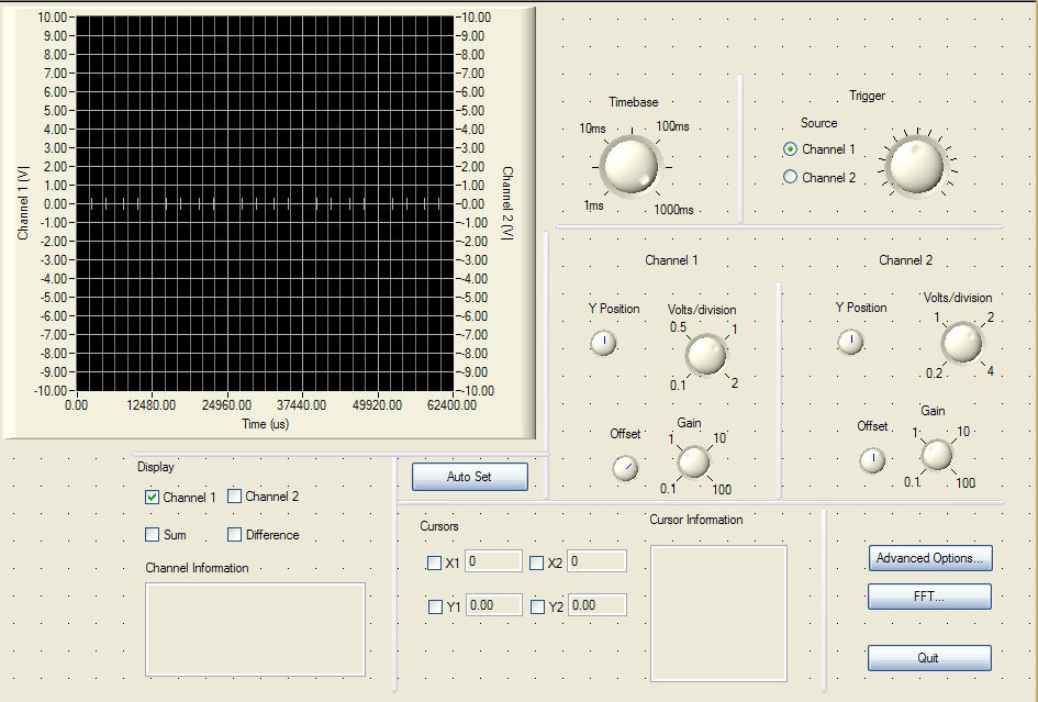
Graph 9: Oscilloscope main window
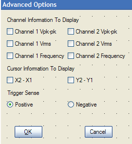
Graph 10: Advanced options screen
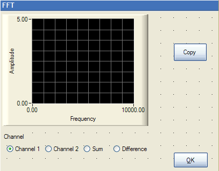
Graph 11: FFT screen
Conclusions:
A working oscilloscope is demonstrated. The user can set offset, gain, axes scaling, cursor positions simply by using a mouse. The scope has a fast sampling frequency and high resolution. Useful calculations such as FFT, sum and difference of two inputs can be performed. It closely mimics the performance of a real oscilloscope but can be cheaply manufactured.