Piano Keyboard Key Transposer
- Introduction
- Mechanical Description
- Hardware Description
- Software Description
- Conclusion
- Pictures
- Demo
- Assembly Code
With the inspiration from lab 3, Digital Waveform Synthesis, I want to make a project that can process and playback music. Some songs are pre-stored in memory. They can be played back just like a real piano keyboard. Also the user can input a song on a simple keyboard that is an octave long. The song is played in real time. Later, the user can ask the 8051 to transpose the song to different keys, or to its parallel minor. This project is interesting and useful because transposing keys is a big part of music theory study.
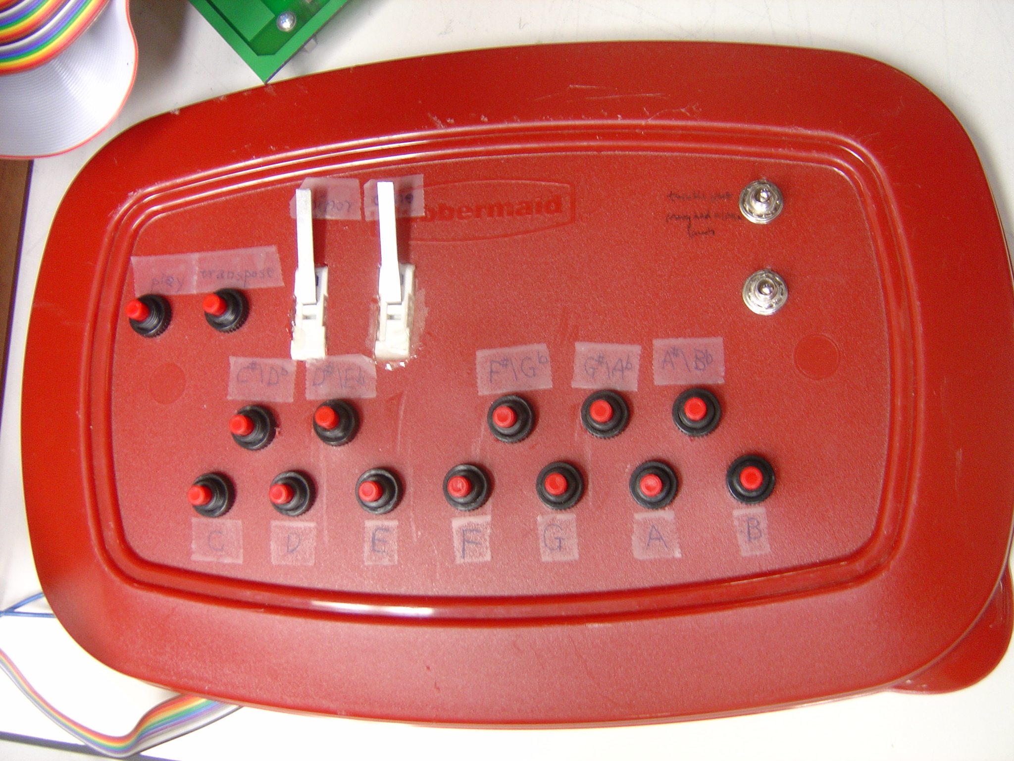
The octave long keyboard is the mechanical part of this project. The layout of the keyboard can be seen in figure 1. To make the hole drilling process easier, a tupperware container top is used as the base of the keyboard. It turned out to be a plus that it provides a bouncy feeling for the fingers. Sixteen momentary switches are the main components of this octave long keyboard. Twelve out of the sixteen switches are the keys in an octave (seven white keys and five black keys). The other four are for user selections (“Play” plays back the song that was input by the user. “Transpose” transposes the stored song to another key. “Minor” transposes the stored song from major to its parallel minor. “Done” should be pressed after the user is done inputting a song.) There are two regular on-off switches on the far right side for selection purposes as well. (The upper one selects between twinkle, twinkle, little star, and Mary and a little lamb. The bottom one selects between playing the stored songs mode and user inputting songs mode).
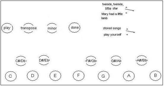
Figure 1: Layout of the octave piano keyboard (18 switches on a tupperware container top)
The electrical connections of the momentary switches are similar to the calculator keypad that is used in class. Figure 2a shows the wiring of the sixteen momentary switches. Figure 2b shows the wiring of the two regular on-off switches.
Figure 2a: The wiring of the sixteen momentary switches. A key hit results a column and a row shorted specifically, and thus the key decoder knows exactly which key is hit
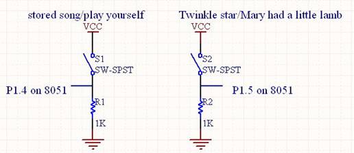
Figure 2b: The wiring of the two regular on-off switches. By reading P1.4 and P1.5 we know if the switches are on or off
The hardware goal of this project is basically making sine waves that have frequencies ranging from ![]() to
to ![]() . This guarantees that we can play all the notes from the three octaves that we use most. The overall picture of the hardware part is shown in figure 3. The one-octave keyboard is decoded by the key decoder 74C922, which is connected to first four pins of Port 1 on R31JP. After a key is received on the keyboard, the 8051 does all the brain work. It reads data from a sine table and sends a value to the DAC every period of time. Then the analog voltage value is scaled, and subtracted, and then fed into LM386, which is a low voltage audio power amplifier. The amplified audio signal is fed to the speaker.
. This guarantees that we can play all the notes from the three octaves that we use most. The overall picture of the hardware part is shown in figure 3. The one-octave keyboard is decoded by the key decoder 74C922, which is connected to first four pins of Port 1 on R31JP. After a key is received on the keyboard, the 8051 does all the brain work. It reads data from a sine table and sends a value to the DAC every period of time. Then the analog voltage value is scaled, and subtracted, and then fed into LM386, which is a low voltage audio power amplifier. The amplified audio signal is fed to the speaker.
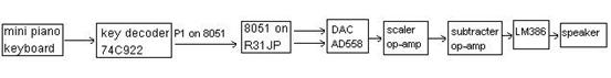
Figure 3: The block diagram of the hardware of the Key Transposer system
While the 8051 is making a sine wave corresponding to the user input in real time, it also stores all the information about each key press, aka, the frequency of the key and the duration the note lasts. The frequency is already determined while the key press is echoed in real time. The duration is calculated using timer interrupt. Once the user hits a note key, a timer is started immediately. The timer is interrupted every 35.58ms. Every time the timer overflows, a dedicated register, R6, will count up one, until the key is released, which is signaled by clearing of the bit P3.5. By counting the number of times the timer overflows, we know exactly how much time it has elapsed for the note. The same strategy is used for counting the rest time between notes. The duration of the note, the rest between notes, along with the frequency of the note, are all stored somewhere in memory. This is how 8051 learns a song.
This strategy requires four timers. We need a timer to make sine wave, a timer to print prompt to the computer screen, a timer to count up until the end of the timer interval, and a timer to count down to retrieve the timer interval. Since 8051 can only provide two timers, I used 8254, a CHMOS Programmable Interval Timer, to generate a square wave with a frequency of 28.1Hz. (The set up of 8254 is to use two counters. Counter 2 in mode 2 triggers counter 1 in mode 1. Load counter 2 with 0xFFFF. Use a crystal oscillator with a frequency of 1.842MHz. Therefore, the frequency of the generated square wave is ![]() .) The output of 8254 is connected to P3.2 and P3.3 on 8051 to generate external interrupt at a frequency of 28.1Hz, because external interrupt is only recognized by a high to low transition. These two external interrupts are faked to be used as two timer interrupts to count time intervals. The full schematics can be found in figure 5 at the end of the report. .
.) The output of 8254 is connected to P3.2 and P3.3 on 8051 to generate external interrupt at a frequency of 28.1Hz, because external interrupt is only recognized by a high to low transition. These two external interrupts are faked to be used as two timer interrupts to count time intervals. The full schematics can be found in figure 5 at the end of the report. .
The block diagram of the storing and playing back processes are shown in figure 4.
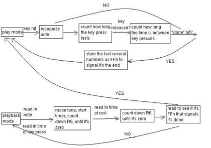
Figure 4: The block diagram of the storing and playing back process
The software part of this project can be divided up into several parts.
*Recognizing notes and echo them back
It probably is feasible to store each note by the frequency of the note. However, Two keys that are a half step apart on a piano keyboard has a ratio of ![]() . It would be really messy and ugly if the microcontroller has to do the calculation. To solve this problem, I used a new numbering system and the table read method to recognize and playback notes. Each musical note has a frequency associated with it. For example, the middle A is 440Hz. We are now using an 8-bit number to represent the same information. The upper nibble stores the octave, and the lower nibble stores the pitch within the octave. (C=0b0000,
. It would be really messy and ugly if the microcontroller has to do the calculation. To solve this problem, I used a new numbering system and the table read method to recognize and playback notes. Each musical note has a frequency associated with it. For example, the middle A is 440Hz. We are now using an 8-bit number to represent the same information. The upper nibble stores the octave, and the lower nibble stores the pitch within the octave. (C=0b0000, ![]() =0b0001, D=0b0002,
=0b0001, D=0b0002, ![]() =0b0003, etc) Therefore, the 440Hz A, which is in the 4 th octave on a real piano key board, is represented as 49h. When converting it to frequency value, we only need to dispatch the higher nibble of the byte, and go to the corresponding table. Clearly each table is an octave long, and the entries in the table store the information about the frequencies of the notes. The lower nibble shows the exact position in the table where we should read the value.
=0b0003, etc) Therefore, the 440Hz A, which is in the 4 th octave on a real piano key board, is represented as 49h. When converting it to frequency value, we only need to dispatch the higher nibble of the byte, and go to the corresponding table. Clearly each table is an octave long, and the entries in the table store the information about the frequencies of the notes. The lower nibble shows the exact position in the table where we should read the value.
To generate sine waves, we use table read. A sine wave is sampled 256 times, and all the data is stored at location 0x1000. Timer 0 is configured to interrupt every 76 ![]() . Every time it gets interrupted, a number that is specific to a frequency is added to the pointer so that a new entry of data is read, and sent to the DAC. Using table read, the skipping step can be read for each note.
. Every time it gets interrupted, a number that is specific to a frequency is added to the pointer so that a new entry of data is read, and sent to the DAC. Using table read, the skipping step can be read for each note.
*Storing the information of a song
There are three pieces of information that are important about a song, the notes, the time the notes last and the time the rests last. Once a note key is pressed, the note is translated into the new numbering system, and is stored at memory location 0x2000. A fake timer (this is mentioned in the hardware description) is fired and it is interrupted every 35.6ms. Every time it gets interrupted, Register 6 counts up by 1, until the note key is released. The chance that R6 will overflow is very unlikely, because the time it takes for R6 to overflow is ![]() . It is very unlikely for a note or a rest to be played for this long. Once the note key is released, the fake timer is stopped, the number in R6 is written following the note, at memory location 0x2001. Then the fake timer is started again to count the rest time. Again R6 is increased every time there is a timer interrupt. The timer is stopped when there is another key hit or the done button is pressed signaling the song is done inputting. The value in R6 is stored following the note time interval at location 0x2002. This whole process repeats for the next note, and the next. The corresponding data are stored one after another. This results in a string of numbers that have all the information of a song. When the user hits the done button, a string of 0xFFs are stored at the end to signal it is the end of the song.
. It is very unlikely for a note or a rest to be played for this long. Once the note key is released, the fake timer is stopped, the number in R6 is written following the note, at memory location 0x2001. Then the fake timer is started again to count the rest time. Again R6 is increased every time there is a timer interrupt. The timer is stopped when there is another key hit or the done button is pressed signaling the song is done inputting. The value in R6 is stored following the note time interval at location 0x2002. This whole process repeats for the next note, and the next. The corresponding data are stored one after another. This results in a string of numbers that have all the information of a song. When the user hits the done button, a string of 0xFFs are stored at the end to signal it is the end of the song.
*Playback the song
Playing back a song carries out a similar principle as storing a song. At location 0x2000, the number is the first note that should be played. A table lookup to is used to get the skipping step for the table read method. The number following it at location 0x2001 says the amount of interrupts the note should be played. 8051 start the second fake timer, and generating the tone while counting down the timer interrupts until that number gets to zero. Then it stops generating the tone, reads from 0x2002. This number tells us how long the rest is supposed to be. The second fake timer is started again. The program counts down timer interrupts until the number gets to zero. Then it is ready generate the next tone. So the data in the next entry are fetched and the loop is repeated. We stop reading the next entry when we read a string of 0xFFs, which signals the end of the song.
*Transposing keys and transposing from major to minor
Once we have the information of a song, we are ready to transpose keys. The quality of the song does not change after the key of the song gets transposed. This means a perfect 5 th is still a perfect 5 th . There are still 7 half steps in between. All the notes in the numbering system increase by half steps, so all we need to do to transpose keys is to add an offset to every note. A prompt is displayed on the screen asking the user to input the key that the song is originally in and the key the user wants the song to be transposed to. Then 8051 can calculate the number of half steps that is between the original key and the transposed key. This is the offset. This offset is added to each note. One thing to note is about overflows. We need to check whether the lower nibble is bigger than 12. If it is, increase the higher nibble by one and the lower nibble by four, so we are reading the right note from the next octave. After the song is played, all the notes are calculated again and displayed on the PC screen. The reason why 8051 cannot display the notes when transposing keys is that the timer interrupt is every 76 ![]() . There are at most 76 machine cycles that can be spent to calculate, to read from table, and such. It turns out that there is not enough time for 8051 to echo the notes while playing.
. There are at most 76 machine cycles that can be spent to calculate, to read from table, and such. It turns out that there is not enough time for 8051 to echo the notes while playing.
Transposing songs to its parallel minor is harder to do. I am just restricting the user to input a song in C major, which is not a bad assumption, because the keyboard is only one octave long. The 8051 flats scale degree 3 and 6 of the C major (E and A in this case).
*Connecting the whole program
Jump back to start after each task (playback, transposing, or changing to minor) is done, so that a new task can be processed.
All the components are working properly. I created a working piano keyboard key transposer!
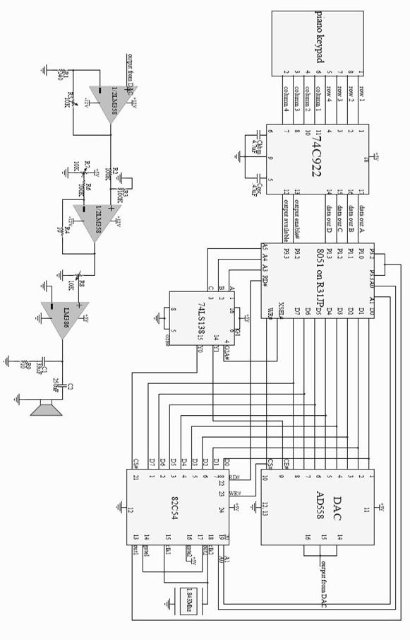
Figure 5: The full schematics of the circuit
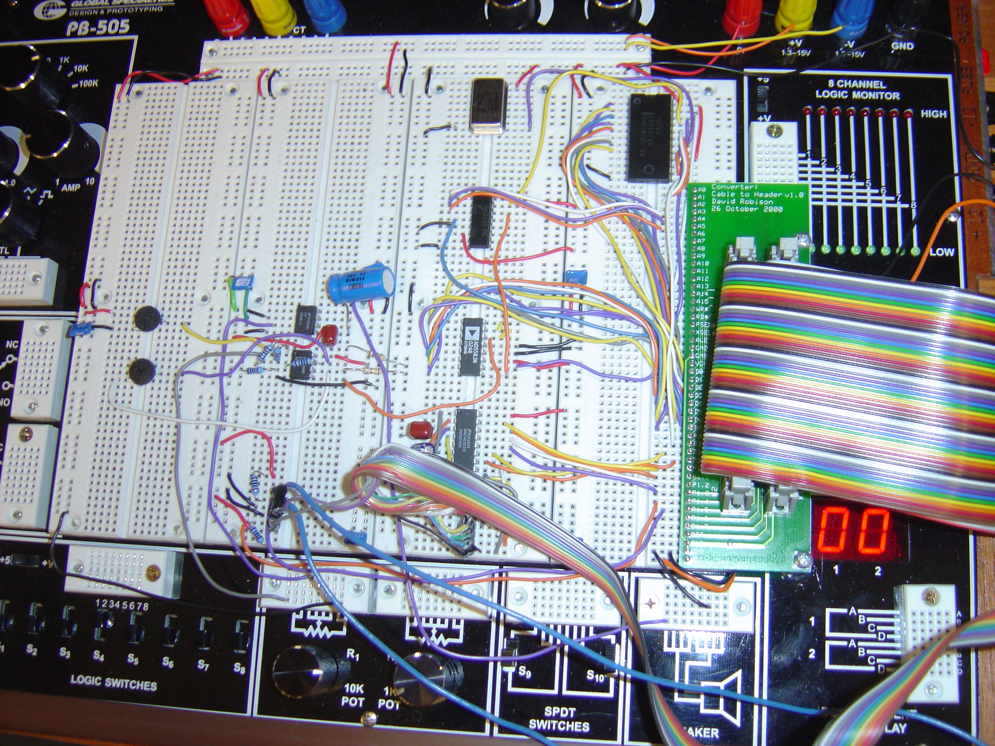
Circuit on the bread board
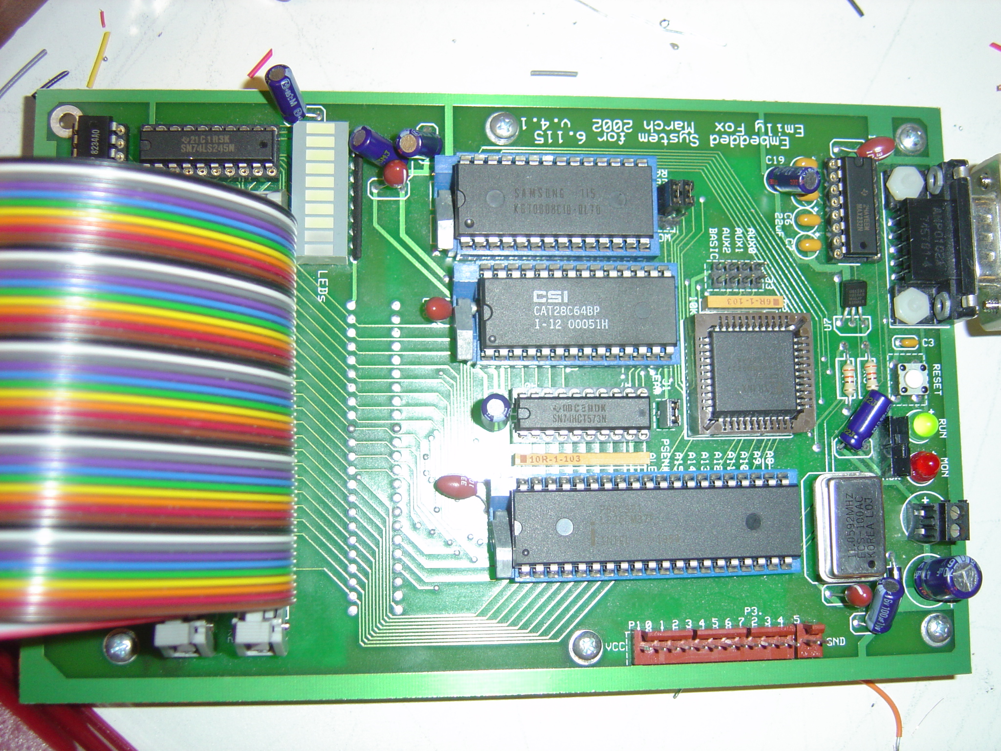
Intel 8051 with extended RAM and ROM
Mechanical part-the piano keyboard
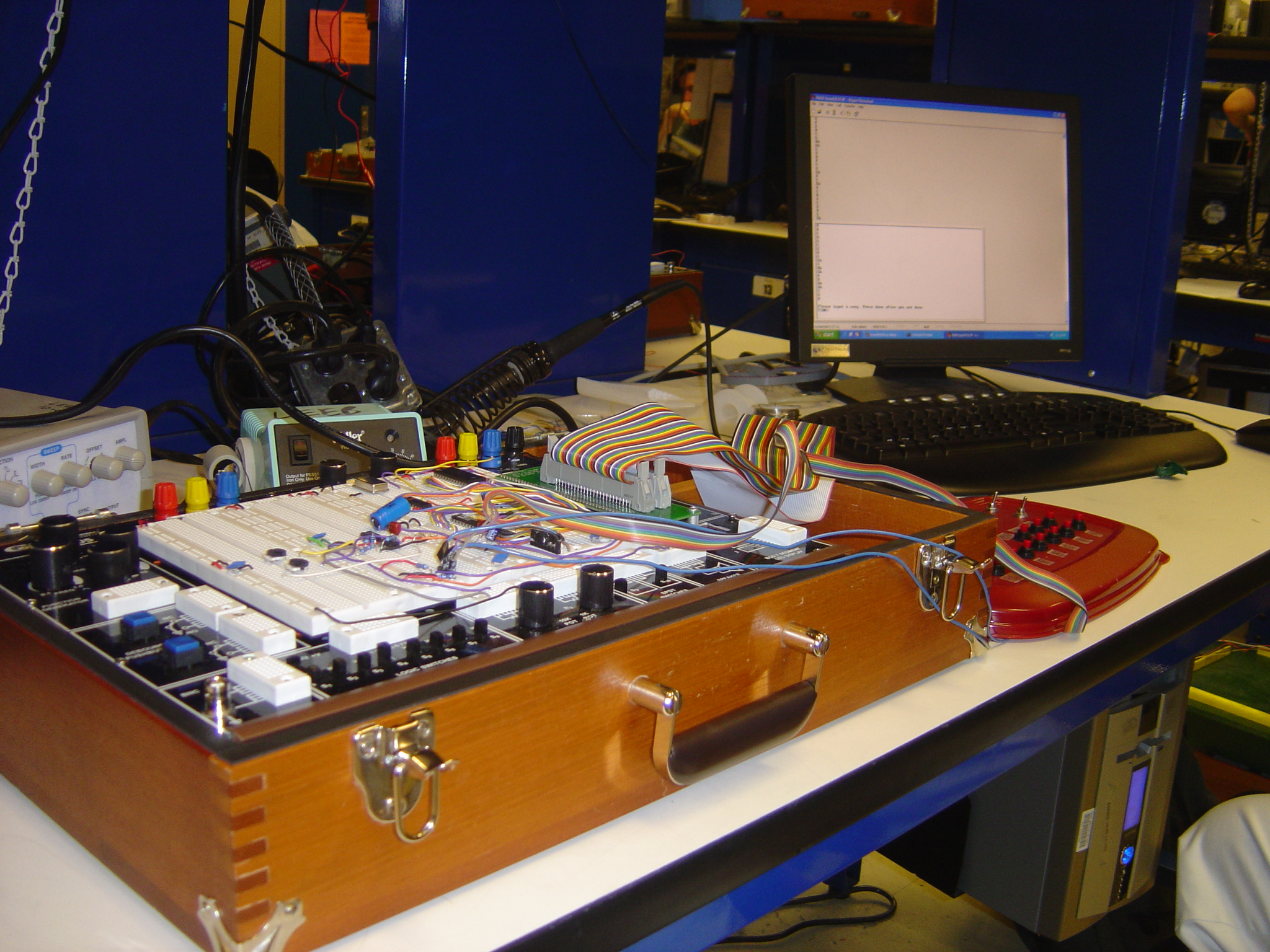
The lab bench