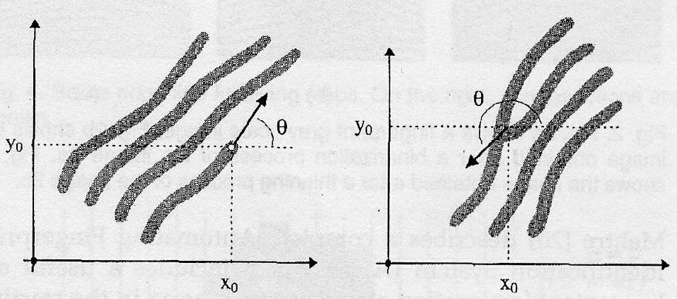
Ridge Tracing and Minutiae Extraction
In a gray scale image (with black the lowest gray value), a ridge line is the local minima along a direction, ie a ridge line corresponds to the dark lines on the fingerprint. A valley is the white areas in between the ridge lines. Thus, we can trace out a ridge line on a fingerprint by connecting the consecutive local minima points and approximating the line with a polygonal line. The minutiae detection process is based on the ridge tracing technique proposed in [5], where a direct tracing of the ridges is done on the original gray-scale image. We find that using direct tracing on the gray-scale image causes some errors to occur, especially if the ridges are close together and and blurred. There is a tendency for the tracing to jump from one ridge line to another , hence giving rise to false minutiae. Here, we propose a novel approach using ridge tracing on the binarized image we obtained in the preprocessing stage.
Our approach uses the same technique proposed in [5], but with a different method to find the local minima. The steps taken in the minutiae extraction process are
1) Superimpose a mesh grid on the binarized image and using each node in the grid as a new starting point.
2) For each starting point, find a point on a close by ridge to start the tracing process.
3) Trace the whole ridge until it exits from window of interest or when the ridge encounters a minutiae.
4) Store the found minutiae, if there is one.
5) When all the ridges have been traced, remove false minutiae from the list we obtained in (4).
We will now describe the ridge tracing process in greater details.
Ridge Tracing
The tracing process can be broken down as follows:
1) Given a starting point (is, js) on a ridge, find the ridge direction of the point (Figure 2) .The ridge direction is found using a technique proposed in [6]. We ensure that the direction found is the direction that we want to trace, by adding or subtracting pi to the angle.

Figure 2.
¡@
2) We take a number of pixels in the direction of the ridge angle to find a new point (ic, jc) on the ridge. In our project, we use a pixel step of 3. The new point we find might be of 2 cases: (i) not on the ridge itself (see Figure 3) or (ii) it might be very close to the edge of the ridge (Figure 4.)
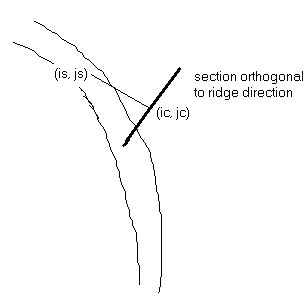
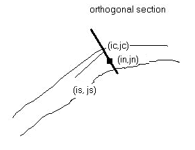
Figure 3. Figure 4.
We take a section of the ridge, of a fixed pixel length, centered at the point (ic, jc) and orthogonal to the ridge direction. In the case where the point (ic, jc) is not on the ridge, we find the closest point to (ic, jc) that is black and take a new section with this point as the center. This will bring us to case (ii). In case (ii), we find the largest interval on the section that has consecutive black pixels and take the midpoint of that interval as our new point. This approach ensures that the ridge tracing is always close to the middle of the ridge and even if there is an error in the ridge direction, our algorithm will take us back onto the ridge. We now call this new point (in, jn).
¡@
3) We test if the ridge tracing should be terminated. The criteria for stopping are:
(i) Exit from window of interest. We define a limiting window on the fingerprint image and if (in, jn) is outside this window, we terminate the tracing. This essentially limits us to finding minutiae inside this window. This is to prevent finding spurious minutiae on the edges of the fingerprint image, which always have a lot of false minutiae.
(ii) Termination. If the angle between (in, jn) and (ic, jc) is more than a threshold, the ridge will have reached a termination point (Figure 5.)
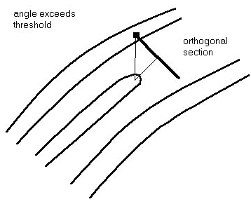
Figure 5.
¡@
(iii) Intersection. If (in, jn) is a point that we have previously labelled as belonging to another ridge, we have found an intersection.
(iv) Excessive bending. The segment between (in, jn) and (ic, jc) forms an angle with the local ridge direction called the relative angle. The local ridge direction is the running average of the previous 3 ridge angles in the tracing. If the relative angle is larger than some threshold, this could be due to errors in the tracing or a termination minutiae has been found, hence we stop the process.
4) Repeat steps (1) - (3) until all the the nodes in the mesh grid has been used.
In the tracing process, we keep track of which ridge has already been traced by the algorithm by doing a polygonal approximation of the ridge line (see Figure 6.)
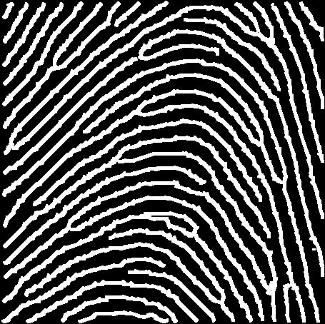
Figure 6.
¡@
Deleting false minutiae
We go through the list of found minutiae and delete those which are
(i) Close together and has ridge angle difference greater than a threshold. This indicates that that the two minutiae are termination minutiae on either sides of a gap in the ridge line or a false minutia due as in Figure 7.
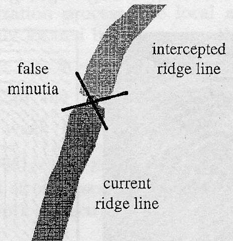
Figure 7.
¡@
(ii) Close together but the angle difference is small. We keep one of the the minutiae and delete the rest.
¡@
An example of the minutiae extracted in shown in Figure 8. The minutiae found are marked with a cross.
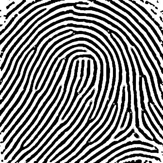
Figure 8.
¡@
Evaluation of our technique
The advantages of this new method are
1) The ridges are much further apart, hence there is a smaller chance for a ridge trace to cross over a valley.
2) Our algorithm ensures that during every stage of the tracing, the trace stays approximately in the middle of a ridge, hence giving a more accurate representation of the topology.
3) Because the noise is removed and enhancement is done on the image, there are less ambiguious ridge endings and spurious minutiae in the image.
However, our new method throws away a lot of the information contained in the original gray-scale image, especially due to the binarization process. This gives rise to inaccurate bifurcation ridge angle. This problem is mainly due to the fact that when tracing starts at different points on the image, the same bifurcation may be detected by tracing either branch of the bifurcation first. The ridge angle thus differs if branch A had been traced first as opposed to branch B (Figure 9.) This angle discrepancy does not affect the termination minutiae, moreover, if the ridge angle is not required to be known, then our algorithm gives a superior performance in finding all the minutiae correctly. Therefore in stage II, we ignore the ridge angle and use other criteria for verification.
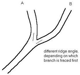
Figure 9.
¡@