The objective of this paper is to enable a see-through-wall technology that is
low-bandwidth, low-power, compact, and accessible to non-military entities. To
this end, the project introduces Wi-Vi (Wi-Fi Vision), a see-through-wall device
that employs Wi-Fi signals in the 2.4 GHz ISM band.
Why is Seeing Through Walls Possible?
The concept underlying seeing through opaque obstacles is similar to radar and
sonar imaging. Specifically, when faced with a non-metallic wall, a fraction of
the RF signal would penetrate the wall, reflect off objects and humans, and come
back imprinted with a signature of what is inside a closed room. By capturing
these reflections, we can image objects behind a wall.
|
|
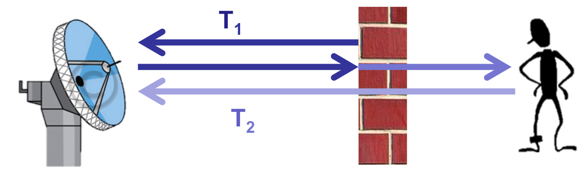
Why is Seeing Through Walls Challenging?
Building a device that can capture such reflections is difficult because the
signal power after traversing the wall twice (in and out of the room) is reduced
by
three to five orders of magnitude . Even more challenging are the
reflections from the wall itself, which are much stronger than the reflections
from objects inside the room. Reflections off the wall overwhelm the receiver's
analog to digital converter (ADC), preventing it from registering the minute
variations due to reflections from objects behind the wall. This behavior is
called the
Flash Effect since it is analogous to
how a mirror in front of a
camera reflects the camera's flash and prevents it from capturing objects in
the scene.
Multiple Antennas to Eliminate the Flash
Existing solutions eliminate the Flash Effect by separating reflections off
the wall from reflections off the objects behind the wall based on their arrival
time. To achieve this separation, these techniquer need to identify sub-nanosecond
delays to filter the flash effect. Therefore, they require blasting
power in multi-GHz of bandwidth, available only to the miliary.
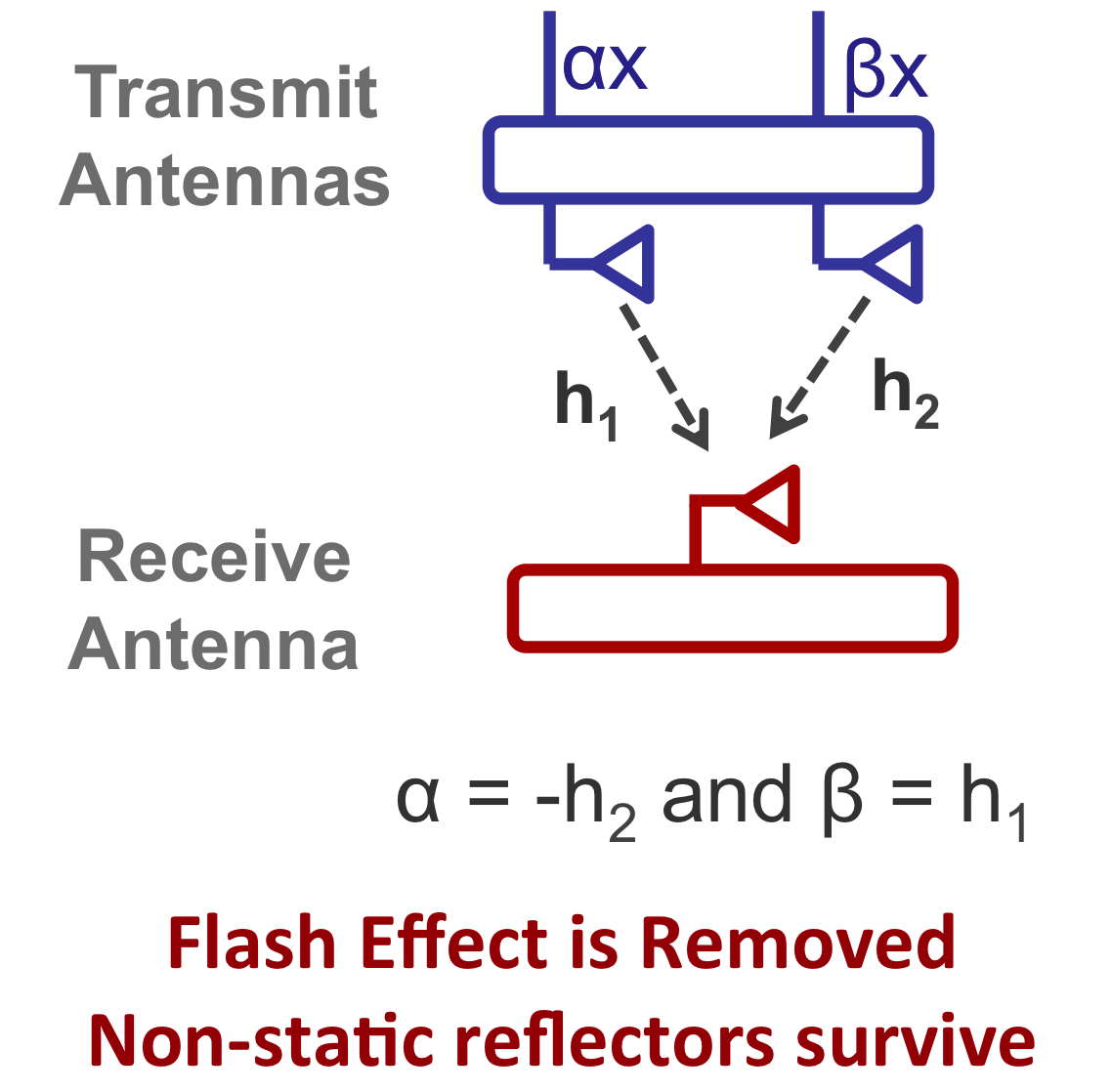
To eliminate the flash effect without using GHz of bandwidth, Wi-Vi encodes its
signal across multiple antennas to cancel out all static reflectors at
the receive antenna. A Wi-Vi device has two transmit antennas and
a single receive antenna. It operates in two stages. In the first stage, it measures the
channels from each of its two transmit antennas to its receive antenna. In stage
2, the two transmit antennas use the channel measurements from stage 1 to null
the signal at the receive antenna. Since wireless signals (including reflections)
combine linearly over the medium, only reflections off objects that move between
the two stages are captured in stage 2. We further refine this basic idea by
introducing iterative nulling, which allows us to eliminate residual flash and
the weaker reflections from static objects behind the wall.
|
|
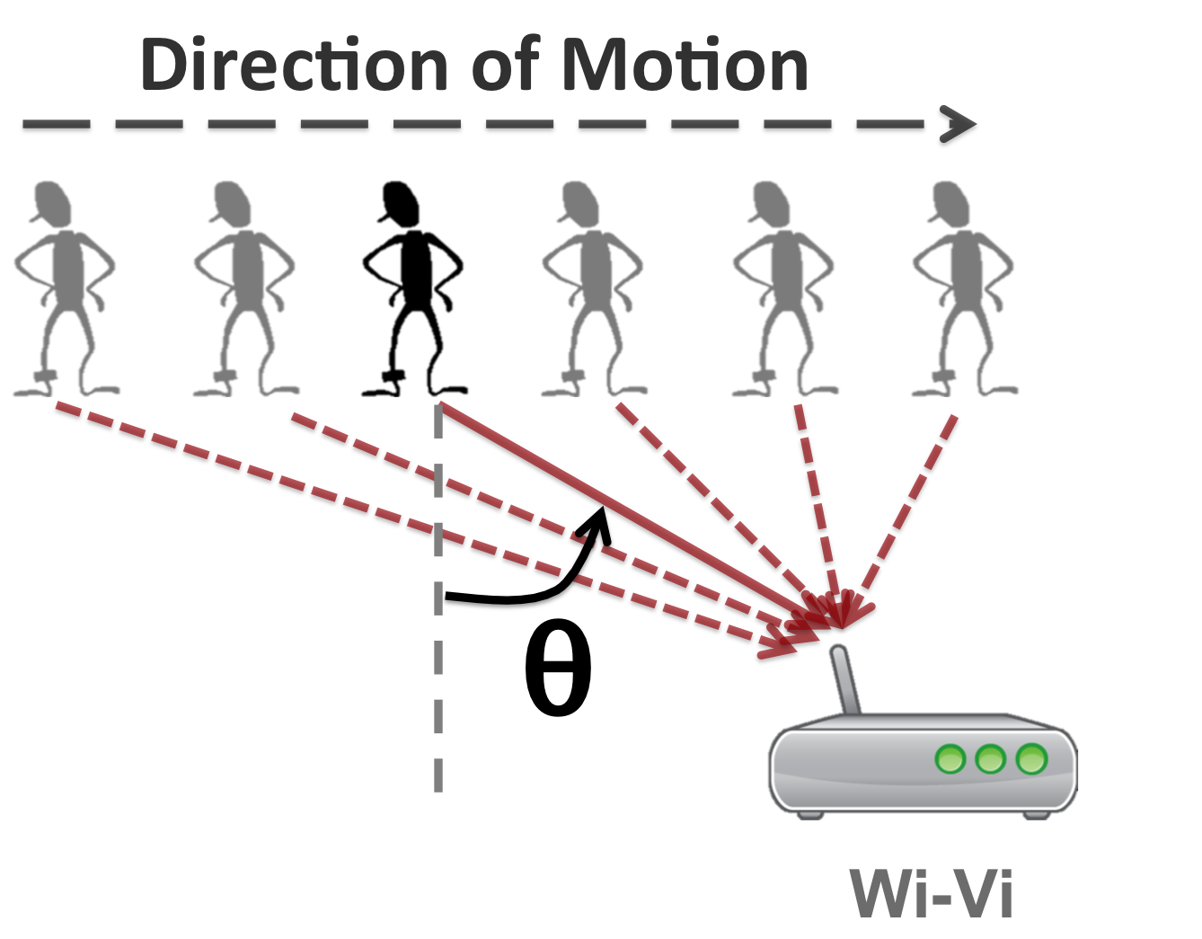
Tracking Human Motion
Wi-Vi also needs to track human motion without using a bulky antenna array. To
that end, borrow a technique called inverse synthetic aperture radar (ISAR),
which has been used for mapping the surfaces of the Earth and other planets.
The technique works as follows: when a person moves, he reflects the transmitted
signal from different points in space. We can conceptually think of the person
as a moving antenna . The device captures consecutive time samples and
treats them as consecutive spatial samples . Using standard antenna array
processing, it is able to indentify the relative angle of the person's motion
with respect to the device. We extend this method to track multiple humans
by using the smoothed MUSIC algorithm .
|
|
A Through-Wall Gesture Interface
Wi-Vi leverages its ability to track motion to enable a through-wall gesture-based
communication channel. Specifically, a human can communicate messages to a Wi-Vi
receiver via gestures without carrying any wireless device. We have picked two
simple body gestures to refer to '0' and '1' bits. A human behind a wall may use
a short sequence of these gestures to send a message to Wi-Vi. After applying a
matched filter, the message signal looks similar to standard BPSK encoding (a
positive signal for a '1' bit, and a negative signal for a '0' bit) and can be
decoded by considering the sign of the signal.