|
| http://people.csail.mit.edu/jaffer/Gamma/video-bw.html |
CRT Video Bandwidth |
If the luminous intensity were a linear function of the video signal, then video frequencies exceeding the speed of the video amplifier would appear as a smooth patch of the average intensity over the patch. But the CRT is a square-law device. Bandwidth limited inputs appear darker than their average intensity.
|
|
|---|
Expressing the time for a full scale slew divided by one half of the
pixel (dot) period as
0 < Rs < 1,
and given conversion exponent g,
with intensities
0 < LL < LA < LH < 1,
the general expression for the averaged intensity is:
LA = Rs * ((LH -
LL)/2)g * (LH -
LL) / (1 + g) + 1/2
(LHg - LLg) *
(1 - Rs * (LH - LL))
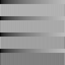
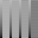
The following chart displays bands of two intensities alternating at the maximum rate interspersed with smooth ramps. Above where a stippled band matches the ramp is the Rs value which theoretically produces that degree of darkening. For a monitor with no slew limitation, the bands will match at the right edge.
 |
|---|
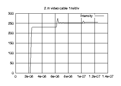
Even the cables linking cards to monitors can introduce artifacts at high speed. In a typical 2 meter coaxial cable with propagation velocity 66% (of c), a reflection reaches the monitor end of the cable 20.ns after the first wavefront. That is 7.6 pixels later at the 375.MHz clock rate driven by a ECS AG315T Video Card.
|
|
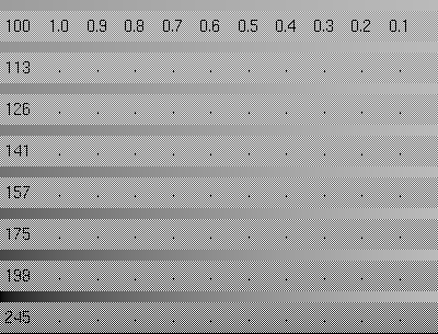
The image on the right is enlarged four times in length. It is oriented with its fast sweep direction downward to isolate its gradations from potential artifacts of your viewing hardware.
The key to visual fidelity on high resolution CRT monitors is to use the slowest available pixel clock for a given resolution.For a given resolution, a slow pixel clock necessitates low horizontal and vertical sweep frequencies. Must one suffer the screen flickering?
For a given resolution and horizontal retrace frequency, vertical interlace doubles the vertical refresh frequency.A surprising consequence of these principles is that classic and modestly priced CRTs and graphics hardware are capable of good color fidelity even at fairly high resolutions.
For example, I have used this XF86Config geometry for years:
# Mode "1536x1152": 115.0 MHz, 57.6 kHz, 90.1 Hz (I) Modeline "1536x1152" 115 1536 1584 1814 1997 1152 1215 1227 1279 interlace |
Slowing down to 75.MHz, R_s measures below 0.20:
# Mode "1536x1152": 75.0 MHz, 37.6 kHz, 58.8 Hz (I) Modeline "1536x1152" 75 1536 1584 1814 1997 1152 1215 1227 1279 interlace |
| Copyright 2001 Aubrey Jaffer | Display Calibration |
|
I am a guest and not a member of the MIT Computer Science and Artificial Intelligence Laboratory.
My actions and comments do not reflect in any way on MIT. | ||
| agj @ alum.mit.edu | Go Figure! | |