|
| http://people.csail.mit.edu/jaffer/cool/SolarScreens |
Solar Screens |
If the solar absorption could be reduced, even at the expense of some infrared emittance, the goal of 24-hour cooling might be possible.
In their 1982 US patent, Silvestrini et al describe a cooling arrangement where the solar-reflective screen is separated from the infrared emitters, which are the objects or people to be cooled. For several configurations they report solar transmittance between 1.1% and 0.6% with infrared transmittance between 43% and 68%.
The solar absorption ranges from 28% to 35%, which would produce heating up to 385 W/m2 at peak solar intensities. In still air, convection transports about 8 W/(m2·K); so one would expect a peak temperature rise of 48 K. Blackbody emissions at 70°C are 75% larger than emissions at 25°C. So the infrared emissivity of the screen becomes important.
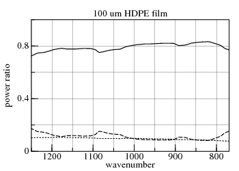 The patent provides measurements for infrared transmission, but not
infrared reflectivity or absorption. Simulating a
100 μm thick HDPE sheet from 8 μm to
13 μm, FreeSnell reports the
average values for transmission, absorption, and reflection are 0.79,
0.11, and 0.10, respectively. The patent gives transmission of the
"starting film" without pigment as 0.85.
The patent provides measurements for infrared transmission, but not
infrared reflectivity or absorption. Simulating a
100 μm thick HDPE sheet from 8 μm to
13 μm, FreeSnell reports the
average values for transmission, absorption, and reflection are 0.79,
0.11, and 0.10, respectively. The patent gives transmission of the
"starting film" without pigment as 0.85.
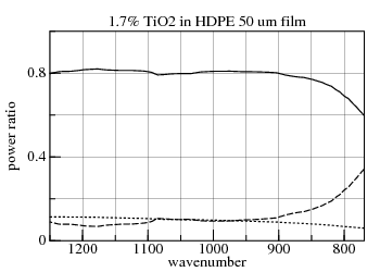 Example 2 of the patent gives an infrared transparency of 0.78 from
8 μm to 13 μm for 7.5% by weight (1.7%
by volume) of TiO2 in 50 μm thick HDPE
sheet. FreeSnell reports the average values for transmission,
absorption, and reflection are 0.79, 0.11, and 0.10, respectively.
Example 2 of the patent gives an infrared transparency of 0.78 from
8 μm to 13 μm for 7.5% by weight (1.7%
by volume) of TiO2 in 50 μm thick HDPE
sheet. FreeSnell reports the average values for transmission,
absorption, and reflection are 0.79, 0.11, and 0.10, respectively.
The lower HDPE sheet of the bi-color screen is filled with carbon-black or cobalt-oxide. Infrared spectral refractive-index data for these materials is not available; and the validity of using Maxwell Garnett Theory to combine the materials is doubtful.
Looking at the (FreeSnell) graphs, the transmission and absorption of the film are complementary, while the reflectance is nearly constant. From these examples, the emissivity being 0.9 minus the infrared-transmission seems a plausible assumption.
Look here for the description of SimRoof's treatment of solar-screens.
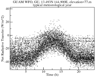
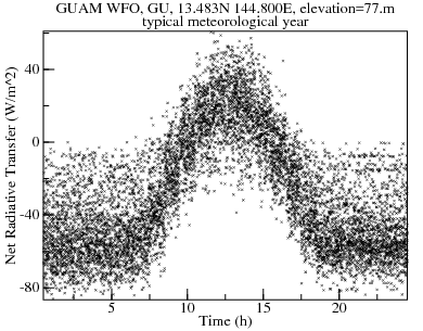
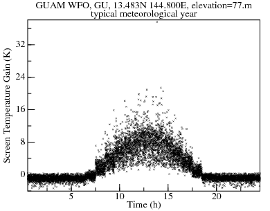
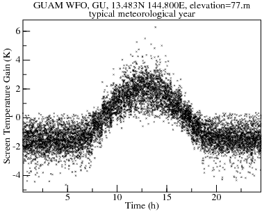
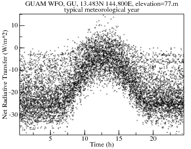
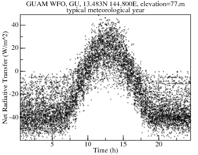
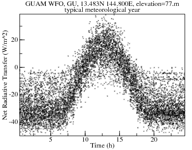
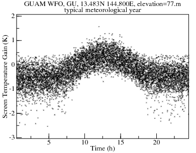
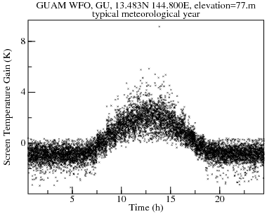
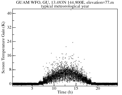
Silvestrini et al test their screen covering a 10 cm deep airspace with a selective radiator at the bottom. Simulated here is the bi-color cover 10 cm above a roof with 80% solar and infrared absorption. The conduction through 10 cm of air is 0.32 W/(m2·K); a larger air gap would give a slight performance improvement.
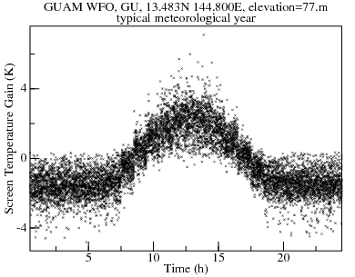
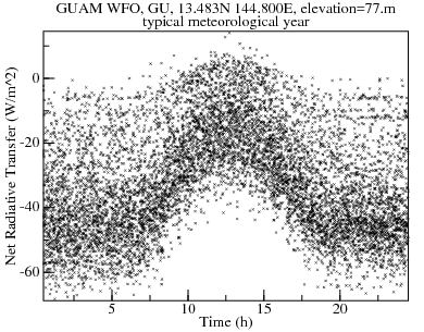
The scatter-plot of roof-heat-gain versus time-of-day on the left shows much less daytime heating than a high-performance CoolRoof on the right. But its night cooling is close to half that of the CoolRoof.
| Bi-color Cover | CoolRoof |
|---|---|
| 
|
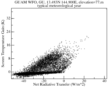
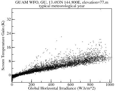
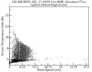
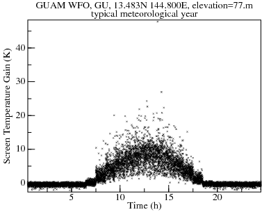
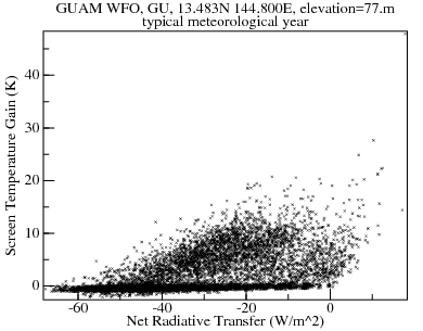
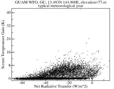
There are 377 hours (4% of 8760) with positive heat gain. These are correlated with the large positive screen-temperature-gains, and occur during periods of low wind-speed.
| 
|
| 
|
The film was produced so that f = 0.15 and d = 400 μm and the optical properties in the solar and thermal parts of the spectrum were Rsol = 0.849, τsol = 0.013, Asol = 0.138, R8-13 = 0.09, τ8-13 = 0.33 and A8-13 = 0.58. In simulations the corresponding optical properties were Rsol = 0.825, τsol = 0.011, Asol = 0.164, R8-13 = 0.059, τ8-13 = 0.520 and A8-13 = 0.421, respectively.Charting those:
Samples TSol RSol ASol T8-13 R8-13 A8-13 15% ZnS in 400 μm thick polyethylene Measured 0.013 0.849 0.138 0.33 0.09 0.58 15% ZnS in 400 μm thick polyethylene Simulated 0.011 0.825 0.164 0.520 0.059 0.421 A 1 mm thick aluminium plate was sprayed with matt black paint several times, with drying in between. By weighing a small reference plate the paint thickness was estimated to be at least 100.um, which makes the plate an almost black body - like emitter of thermal radiation. Spectrophotometric measurements showed that the painted plate had R_sol = 0.045 which means that Asol = 0.955. In the thermal spectral region the corresponding values were R8-13 = 0.09 and A8-13 = 0.91.
...
The ZnS pigmented foil was subsequently fixed to cover the box at a height of 50 mm above the radiator.
| Chalmers Cover | Bi-color Cover |
|---|---|

|
|
|
|
There are 995 hours (11% of 8760) with positive heat gain. The performance is not as good as the bi-color screen due primarily to the black roof. Replacing it with a white roof and increasing the separation to 10 cm brings the daytime cooling closer to the bi-color screen (481 vs 377 hours of positive heat gain). Night cooling is also inferior because of the polyethylene thickness being 400 μm vs 100 μm.
| Chalmers Cover over White Roof | Bi-color Cover |
|---|---|
|
|
|
|
Table 1
Optical functions values, R8-13, A8-13, T8-13, RSol, TSol and ASol as defined in the text.Sample T8-13 R8-13 A8-13 TSol RSol ASol Polyethylene 0.813 0.156 0.030 0.891 0.078 0.031 Mn-O coated polyethylene 0.801 0.170 0.029 0.725 0.173 0.102 Te Film 0.652 0.221 0.137 0.047 0.123 0.830
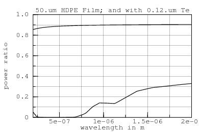
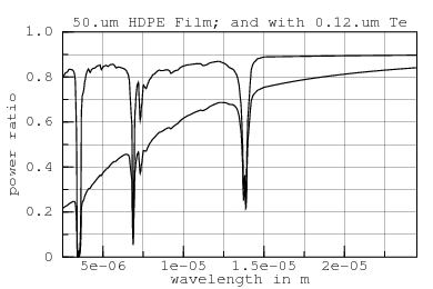
With the Te layer on top, the reflection and absorption from top and bottom differ. FreeSnell calculates the following values for 50 μm HDPE (not LDPE) without and with a 0.12 μm layer of Te on top:
Sample Side T8-13 R8-13 A8-13 TSol RSol ASol HDPE either 0.914 0.085 0.0 0.841 0.101 0.058 Te Film on HDPE top 0.610 0.349 0.042 0.078 0.563 0.358 Te Film on HDPE bottom 0.610 0.321 0.070 0.078 0.470 0.450
Tellurium 8-13 numbers are reasonably close to those measured by Engelhard et al, but the solar numbers are not. FreeSnell's simulation of the HDPE with tellurium (ordinary-ray) in the infrared (on right) matches well with the graph in the paper; but the solar response (on left) has more than 3 times the transmission.
| 
|
Neither changing to the extraordinary-ray nor varying the tellurium thickness resolves the difference; and such changes spoil the infrared match.
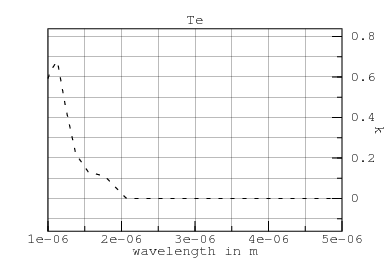
The problem is that tellurium is a semiconductor. Room-temperature tellurium has a direct band-gap of 0.32 eV (3.87 μm), which lies in between the two wavelength regions plotted. Solar radiation, nearly all of which has more energy than 0.32 eV, will be absorbed and inject carriers into the conduction band. That carrier cloud in turn makes the tellurium more metal-like and reflective.
That would be good news except that those carriers will also reflect thermal-infrared radiation. A screen covered with tellurium will not allow radiative cooling during daylight! An unscreened CoolRoof will have better daylight performance than tellurium screens.
The only loose end is why (in the plot to the right) does the absorption transition occur at 2 μm rather than 3.87 μm?
"The ideal shield should secure complete reflection of the solar radiation and complete transmission of the IR window region (8-13 μm)."
Table 1. Optical Function Values of the Different TiO2 Pigmented Shields sample TiO2film thickness (μm) TSol RSol ASol T8-13 R8-13 A8-13 A 0.12 0.610 0.381 0.009 0.765 0.172 0.063 B 0.45 0.412 0.581 0.007 0.731 0.154 0.115 C 0.75 0.273 0.712 0.015 0.681 0.162 0.157 D 1.08 0.220 0.684 0.096 0.651 0.153 0.196 E 1.82 0.166 0.763 0.071 0.546 0.178 0.276 sub-μm TiO2 0.323 0.601 0.076 0.391 0.174 0.435 PE 0.891 0.078 0.031 0.813 0.151 0.036
| Mastai et al Sample C | Mastai et al Sample E |
|---|---|
| 
|
Unfortunately, they sacrificed solar reflection in the pursuit of transparency. Even for example E (the highest reflection sample) too much solar radiation reaches the roof, overwhelming cooling during daylight hours.
"... these measurements underestimate the transmittance values, since scattered transmitted radiation is not counted."
Higher solar transmittance only makes the daytime situation worse.
| Mastai et al Sample C | Mastai et al Sample E |
|---|---|
| 
|
| 
|
The semiconductors PbS and PbSe have (300 K) direct bandgaps of 0.37 eV and 0.26 eV, respectively. As with Tellurium-coated films, the charge carriers generated by solar absorption will allow only negligible radiative cooling during daylight.
Table 1
Values of the optical functions, R8-13, A8-13, T8-13, RSol, TSol and ASol, of various materials for application in radiative cooling devices.Samples TSol RSol ASol T8-13 R8-13 A8-13 LDPE 50 mm 0.891 0.078 0.031 0.813 0.156 0.031 Pigmented ZnS (50 mm) 0.346 0.540 0.114 0.641 0.193 0.166 Pigmented ZnO (50 mm) 0.403 0.429 0.168 0.582 0.184 0.234 PbSe HC NTA (200 nm) T=25°C 0.09 0.274 0.636 0.508 0.186 0.306 PbS HC NTA (200 nm) T=25°C 0.168 0.468 0.364 0.741 0.154 0.105 PbS HC TSC (150 nm) T=25°C 0.138 0.372 0.490 0.642 0.143 0.215 Pigment ZnS coated with PbS film 0.04 0.331 0.629 0.488 0.162 0.350 Pigment ZnO LDPE coated with PbS film 0.03 0.286 0.684 0.406 0.155 0.439
For deployment above a roof, the bi-color screen is over-designed in that the black bottom layer is not needed if the roof itself reflects solar radiation. Covering the CoolRoof analyzed earlier with just the white HDPE sheet (10 cm air gap) reduces the solar heating and increases the infrared emissions so that there are only 217 (2.5% of 8760) hours of net roof heat gains. Other than one hour at 22 W/m2, the net heating of the roof over a typical year is always less than 12 W/m2. Because the thermal transmission of the screen improves from 0.62 to 0.78, the nighttime cooling is 80% of that for the CoolRoof alone and 36% greater than for the bi-color screen.
| Covered CoolRoof | Bi-color Cover |
|---|---|
|
|
The peak screen heating is actually greater than for the bi-color screen. But because the screen's emissivity is lower, screen heating contributes less to roof heating.
| Covered CoolRoof | Bi-color Cover |
|---|---|
|
|
The bi-color cover cools itself (not the roof) below ambient more than the covered cool-roof. Again, this is because the thicker screen is more emissive, reducing the cooling available to the roof.
| Covered CoolRoof | Bi-color Cover |
|---|---|
|
|
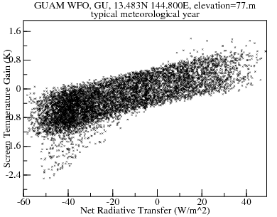
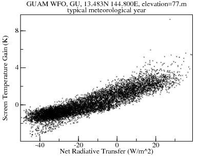
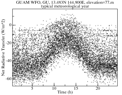
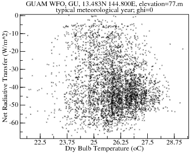
Plotting net-radiative-transfer against ambient (dry-bulb) temperature shows that, while night cooling is nearly always available, day cooling is not reliable.
| Covered CoolRoof—Diurnal Cooling | Covered CoolRoof—Nocturnal Cooling |
|---|---|
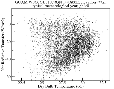
| 
|
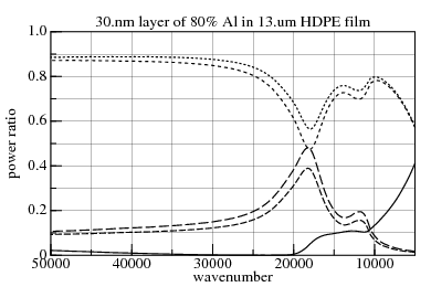
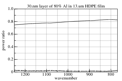
| Reflection, Absorption, Transmission, 0.2 μm−2.0 μm | Transmission, Absorption, 8 μm−13 μm |
| 
|
FreeSnell Simulation Sample Side TSol RSol ASol T8-13 A8-13 30.nm layer of 80% Al in 13.um HDPE film top 0.118 0.722 0.159 0.795 0.017 30.nm layer of 80% Al in 13.um HDPE film bottom 0.118 0.679 0.202 0.795 0.019
| |
| 
|
There are 232 hours of net heat gain, nearly all of them less than +12 W/m2.
Copyright © 2010 Aubrey Jaffer
|
I am a guest and not a member of the MIT Computer Science and Artificial Intelligence Laboratory.
My actions and comments do not reflect in any way on MIT. | ||
| Radiative Cooling in Hot Humid Climates | ||
| agj @ alum.mit.edu | Go Figure! | |